
Related Manuals for Bailey Infi 90 IMFBS01


Summary of Contents for Bailey Infi 90 IMFBS01
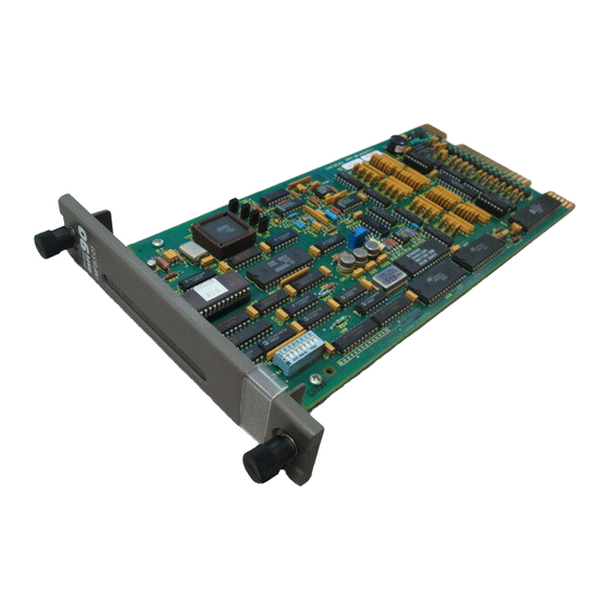
- Page 1 E96-302 ® ® Field Bus Slave Module (IMFBS01) Process Control and Automation Solutions from Elsag Bailey Group...
- Page 2 The information contained in this document is subject to change without notice. Elsag Bailey, its affiliates, employees, and agents, and the authors and contributors to this publication specif- ically disclaim all liabilities and warranties, express and implied (including warranties of merchantability and...
- Page 3 The system engineer or technician using the FBS module should read and understand this instruction before installing and operating the module. In addition, a complete understand- ing of the INFI 90 system is beneficial. ® INFI 90 is a registered trademark of Elsag Bailey Process Automation. I-E96-302B...
- Page 4 ® List of Effective Pages Total number of pages in this instruction is 54, consisting of the following: Page No. Change Date Preface Original List of Effective Pages Original iii through vi Original 1-1 through 1-7 Original 2-1 through 2-12 Original 3-1 through 3-5 Original...
- Page 5 ® Safety Summary GENERAL Equipment Environment WARNINGS All components, whether in transportation, operation or storage, must be in a noncorrosive environment. Electrical Shock Hazard During Maintenance Disconnect power or take precautions to insure that contact with energized parts is avoided when servicing. SPECIFIC Disconnect power before installing dipshunts on the module mount- WARNINGS...
-
Page 6: Table Of Contents
Table of Contents Page SECTION 1 - INTRODUCTION ....................1-1 OVERVIEW ........................1-1 INTENDED USER ......................1-1 HARDWARE DESCRIPTION..................1-1 HARDWARE APPLICATION...................1-2 FEATURES........................1-3 INSTRUCTION CONTENT .....................1-4 HOW TO USE THIS INSTRUCTION ................1-4 GLOSSARY OF TERMS AND ABBREVIATIONS .............1-5 REFERENCE DOCUMENTS..................1-6 NOMENCLATURE ......................1-6 SPECIFICATIONS ......................1-7 SECTION 2 - DESCRIPTION AND OPERATION................2-1 INTRODUCTION......................2-1 SYSTEM OPERATION ....................2-1... - Page 7 ® Table of Contents (continued) Page SECTION 5 - OPERATING PROCEDURES................5-1 INTRODUCTION ......................5-1 START-UP........................5-1 OPERATION......................... 5-2 IMFBS01 STATUS LED ....................5-3 SECTION 6 - TROUBLESHOOTING...................6-1 INTRODUCTION ......................6-1 ERROR MESSAGES AND CORRECTIVE ACTION ............6-1 Status Reports ...................... 6-1 Missing I/O Module Error ..................
- Page 8 List of Figures Title Page 1-1. INFI 90 Communication Levels................1-2 2-1. Field Bus Mode ......................2-1 2-2. FSK Analog Point-to-Point Mode................2-3 2-3. Baseband Analog Point-to-Point Mode ..............2-4 2-4. IMFBS01 Functional Block Diagram ..............2-5 2-5. Digital Input Circuit ....................2-8 2-6. Analog Input Filter and Overvoltage Protection ............2-9 2-7.
-
Page 9: Section 1 - Introduction
(TU) or termi- nation module (TM). Wiring from the field devices connect to terminal blocks on the termination unit or termination module. ® Network 90 is a registered trademark of Elsag Bailey Process Automation. OVERVIEW I-E96-302B... -
Page 10: Hardware Application
The FBS module can operate in one of three modes: FSK field bus mode, FSK analog point-to-point mode, or baseband analog point-to-point mode. In the FSK field bus mode, a single ® INFI-NET is a registered trademark of Elsag Bailey Process Automation. HARDWARE APPLICATION 1 - 2... -
Page 11: Features
Baseband analog point-to-point mode allows the FBS module to emulate the IMASI02 Analog Input Slave Module. In this mode, the module can interface Bailey -Fischer & Porter FSK smart transmitters, baseband smart transmitters, conven- tional transmitters and other external analog inputs. Only the Bailey-Fischer &... -
Page 12: Instruction Content
Explains how to replace a module needing repair. Procedures Support Services Provides information about ordering parts from your local Bailey Controls Company sales office. It also explains other areas of support that Bailey Controls Company provides. Appendix A Shows the dipshunt settings, terminal wiring for the analog input termination unit and the cabling needed for the FBS module. -
Page 13: Glossary Of Terms And Abbreviations
Bailey Controls Company offers. GLOSSARY OF TERMS AND ABBREVIATIONS Table contains those terms and abbreviations that are unique to Elsag Bailey or have a definition that is different from standard industry usage. Table 1-1. Glossary of Terms and Abbreviations Term Definition Control Module Directs field processes through an I/O module;... -
Page 14: Reference Documents
INTRODUCTION ® REFERENCE DOCUMENTS Table lists Elsag Bailey instructions referenced in this instruction. Table 1-2. Reference Documents Number Title C-E96-110 Operator Interface Station C-E96-800 Engineering Workstation I-E21-28 Smart Transmitter Terminal, Type STT02 I-E21-28-1 Smart Transmitter Terminal, Type STT02E I-E92-501-2 Configuration and Tuning Terminal, Type CTT02... -
Page 15: Specifications
INTRODUCTION SPECIFICATIONS Table contains the specifications for the IMFBS01 module. Table 1-4. Specifications Property Characteristic/Value Power requirements Operating power 5 VDC, ±5% at 85 mA typical +15 VDC, ±5% at 25 mA typical -15 VDC, ±5% at 20 mA typical Power dissipation 1.1 W typical Installation category... -
Page 16: Section 2 - Description And Operation
The digital interface, made up of the FBS module and the con- trolling module, provides a communication path between an INFI 90 operator interface and Bailey-Fischer & Porter smart transmitters as shown in Figure 2-1. Commands can be sent from an operator interface to change transmitter parameters or to rerange a transmitter output. -
Page 17: Imfbs01 Module
DESCRIPTION AND OPERATION ® begins when the controlling module is placed in the execute mode with function code 132, and optionally with function code 133, in its configuration. When the controlling module enters the execute mode, it downloads the operating strategy to the FBS module. -
Page 18: Imfbs01 Modes Of Operation
FSK Field Bus Mode The FSK field bus mode allows pure digital communication with Bailey-Fischer & Porter FSK smart transmitters on a bus (Fig. 2-1). Examples of the FSK line of smart transmitters are the PTS and BCN smart pressure transmitters, EQN smart temperature transmitter and Type TBN580 smart pH/ORP smart transmitter. -
Page 19: Baseband Analog Point-To-Point Mode
IMASI02 Analog Input Slave Module, which was the predecessor to the FBS module. When operating in this mode, the FBS module can interface any combination of Bailey -Fis- cher & Porter FSK smart transmitters, baseband smart trans- mitters, conventional transmitters and other analog inputs. -
Page 20: Imfbs01 Operation
I/O FIFO TP25179A Figure 2-4. IMFBS01 Functional Block Diagram The FBS module interfaces Bailey-Fischer & Porter smart transmitters to the controlling module (MFP/MFC). It does this by encoding and decoding communication and data that is going to and coming from the transmitters. Under normal oper- ation, the FBS module continuously inputs, converts and stores data so that it is available to the controlling module. - Page 21 DESCRIPTION AND OPERATION ® The microprocessor directs and coordinates the operation of the functional blocks that make up the FBS module. The mod- ule stores (in memory) the transmitter configurations it receives from the controlling module during start-up. The microprocessor uses this information to monitor transmitter status.
-
Page 22: Module Input/Output Circuitry
I/O expander bus interface. The MFP module communicates with the FBS module over the I/O expander bus. An Elsag Bailey designed integrated circuit interfaces the microprocessor to the I/O expander bus. All MFP commands and process data pass through the I/O expander bus interface and first in first out inputs or outputs. -
Page 23: Fsk Digital Inputs (Field Bus Mode)
DESCRIPTION AND OPERATION ® FSK DIGITAL INPUTS (FIELD BUS MODE) In the field bus mode, all data and communication are FSK encoded digital signals on a shared bus and require decoding. The microprocessor can read any input by specifying the bus address of the device. -
Page 24: Communication Circuitry
DESCRIPTION AND OPERATION baseband communication mode, the input passes through the baseband communication circuitry for decoding. The micro- processor coordinates operation of point-to-point input and output through three sets of multiplexers (analog input, FSK and baseband). Figure shows a typical analog input filter circuit. The cir- cuit shown in Figure connects to the FBS termination (point-to-point) through the P3 connector. -
Page 25: Fsk Communication
DESCRIPTION AND OPERATION ® FSK COMMUNICATION The FBS module can use FSK digital communication in the field bus mode or point-to-point mode. When the microproces- sor enables the FSK receive gate, digital signals from an FSK style smart transmitter enter the FSK communication cir- cuitry. -
Page 26: Baseband Communication
DESCRIPTION AND OPERATION t = 0 FSK INPUT SIGNAL AT 9600 BAUD DIGITAL OUTPUT FROM DECODING LOGIC TP25184A Figure 2-8. FSK Signal and Decoded Digital Equivalent To transmit, the microprocessor enables the FSK transmit gate. The microprocessor transmits a digital signal that passes through encoding logic to an oscillator circuit. -
Page 27: I/O Expander Bus Interface
DESCRIPTION AND OPERATION ® REFERENCE FEEDBACK AND VOLTAGE ZEROING AMPLIFIER ANALOG TO DUAL SLOPE BUFFERS AND DIGITAL FILTERED INPUT INTEGRATOR/ OPERATION DIFFERENTIAL ANALOG MULTIPLEXERS DE-INTEGRATOR AMPLIFIER SELECT INPUTS MULTIPLEXER ANALOG TO ZERO-CROSSING DIGITAL DETECTOR CONTROL CHIP MICROPROCESSOR TP25185A Figure 2-9. Analog to Digital Conversion Circuitry signal to a single ended voltage. -
Page 28: Section 3 - Installation
Observe these steps when handling electronic circuitry: NOTE: Always use Elsag Bailey’s field static kit (part number 1948385_1 - consisting of two wrist straps, ground cord assembly, alligator clip, and static dissipating work surface) when working with static sensitive devices. -
Page 29: Unpacking And Inspection
1. Examine the module to make sure that no damage has occurred in transit. 2. Notify the nearest Elsag Bailey sales office of any damage. 3. File a claim for any damage with the shipping company that handled the shipment. -
Page 30: Imfbs01 Dipswitch And Jumper Settings
INSTALLATION IMFBS01 DIPSWITCH AND JUMPER SETTINGS There is one dipswitch (S1) and four jumpers (J1-J4) that must be set before installing the FBS module. The single dipswitch sets the I/O expander bus address. The jumpers set the operating and communication mode. Module Address Selection Switch (S1) The FBS module must have a unique address on the I/O expander bus. -
Page 31: Operating Mode Jumper (J1)
INSTALLATION ® Operating Mode Jumper (J1) The operating mode jumper sets the FBS operation to point-to-point mode or field bus mode. Set jumper J1 for the desired operating mode. Table lists the jumper settings for J1. Figure shows the location of J1 on the FBS circuit board. -
Page 32: Termination Unit Or Module Installation
INSTALLATION Termination Unit or Module Installation Wiring from field devices connect to the INFI 90 system through terminal blocks on a termination unit or module. If installing the FBS module in the point-to-point mode, use the NTAI05 Analog Input Termination Unit (refer to Appendix A) or the NIAI04 Analog Input Termination Module (refer to... -
Page 33: Section 4 - Calibration
SECTION 4 - CALIBRATION INTRODUCTION The FBS analog inputs are calibrated in the factory, eliminat- ing the need for calibration during installation. However, from time to time (during plant maintenance and routine calibration checks), the module analog inputs may need adjustment. Use the calibration procedure in this section to check the FBS calibration. - Page 34 16. Repeat Steps 1 through 11 with any other input channel to verify the calibration. 17. If any input channel is not within tolerance, replace the module or contact your nearest Elsag Bailey service represen- tative. Completing this calibration procedure also calibrates all other input ranges listed in Table 1-4.
-
Page 35: Section 5 - Operating Procedures
SECTION 5 - OPERATING PROCEDURES INTRODUCTION This section explains the start-up and operating procedures for the FBS module. START-UP To start up the FBS module: 1. Apply power to the FBS module. 2. Place the controlling module (MFP/MFC) in execute mode. Communication between the FBS module and the controlling module begins automatically if there are no configuration errors and the controlling module is in the execute mode. -
Page 36: Operation
OPERATING PROCEDURES ® OPERATION Normal operation begins after the FBS module completes the communication checks of all input channels. During opera- tion, the function code specifications can be tuned through an INFI 90 operator interface to make changes in transmitter operating parameters and calibrate outputs. -
Page 37: Imfbs01 Status Led
Figure shows the location of the status LED on the FBS faceplate. Refer to Table for a list of LED states and their meaning. Bailey RED/GREEN STATUS LED TP25181A Figure 5-2. IMFBS01 Status LED Table 5-1. IMFBS01 Status LED States... -
Page 38: Section 6 - Troubleshooting
SECTION 6 - TROUBLESHOOTING INTRODUCTION This section explains how to detect FBS errors and the correc- tive action to take for those errors. ERROR MESSAGES AND CORRECTIVE ACTION Status reports from the control module are available through any INFI 90 operator interface such as an operator interface station (OIS), configuration and tuning terminal (CTT) or an AT compatible computer with the Smartport (SEEK) soft- ®... -
Page 39: Missing I/O Module Error
TROUBLESHOOTING ® Table 6-1. IMFBS01 Error Codes Error Description Corrective Action No FBS module Check FBS jumper and switch settings. response or wrong Replace the IMFBS01 if jumper and switch module type settings check good. Check function code 132 for correct specifica- tion values, such as I/O module address. -
Page 40: Blinking Green Status Led
TROUBLESHOOTING module configuration (function code 132). This error appears in the status bytes of the control module (bytes three through five). A missing I/O module error sets byte three equal to 03 and bytes four and five equal to the block number of the miss- ing I/O module. -
Page 41: P2 Edge Connector Pin Assignments
TROUBLESHOOTING ® Table 6-4. P2 Edge Connector Pin Assignments Connection Connection Connection Data 1 Data 5 BCLOCK Data 0 Data 4 SYNC Data 3 Data 7 Not used Data 2 Data 6 Table 6-5. P3 Input Signal Pin Connections Group A Group B Connection Connection... -
Page 42: Section 7 - Maintenance
The reliability of any stand-alone product or control system is affected by the maintenance of the equipment. Elsag Bailey recommends that all equipment users practice a preventive maintenance program that will keep the equipment operating at an optimum level. -
Page 43: Equipment And Tools Required
MAINTENANCE ® Table 7-1. Preventive Maintenance Schedule Task Frequency Check cabinet air filters. Clean or replace them as necessary. Check the air filter more 3 months frequently in excessively dirty environments. Check cabinet and IMFBS01 for dust. Clean as necessary using an antistatic vacuum. Check all FBS signal, power and ground connections within the cabinet. -
Page 44: Printed Circuit Board Cleaning
MAINTENANCE Printed Circuit Board Cleaning There are several circuit board cleaning procedures in this sec- tion. These procedures cover circuit board cleaning and wash- ing, cleaning edge connectors and circuit board laminate between edge connectors. Use the procedures that meet the needs of each circuit board. - Page 45 MAINTENANCE ® To clean tarnished or deeply stained edge connector contacts: 1. Use an Eberhard Faber (400A) pink pearl eraser or equiva- lent to remove tarnish or stains. Fiberglass or nylon burnish- ing brushes may also be used. 2. Minimize electrostatic discharge by using the 80/20 iso- propyl alcohol/water solution during burnishing.
-
Page 46: Section 8 - Repair And Replacement Procedures
SECTION 8 - REPAIR AND REPLACEMENT PROCEDURES INTRODUCTION This section explains the replacement steps for an FBS mod- ule. There are no special tools required to replace the module. MODULE REPAIR AND REPLACEMENT If the FBS module is faulty, replace it with a new one. Do not try to repair the module;... -
Page 47: Section 9 - Support Services
SECTION 9 - SUPPORT SERVICES INTRODUCTION Bailey Controls Company is always ready to assist in the oper- ation and repair of its products. Send requests for sales or application services to the nearest sales or service office. Bailey Controls Company can also provide installation, repair and maintenance contract services. -
Page 48: Appendix A - Ntai05 Termination Unit Configuration
APPENDIX A - NTAI05 TERMINATION UNIT CONFIGURATION INTRODUCTION The FBS module uses the NTAI05 termination unit for point-to-point operation. Select the input type of each channel through the dipshunts on the termination unit. The FBS mod- ule can accept inputs of four to 20 milliamps, one to five VDC, zero to one VDC, zero to five VDC, zero to ten VDC and -10 to +10 VDC. -
Page 49: Configuring Inputs
NTAI05 TERMINATION UNIT CONFIGURATION ® Table A-1. NTAI05 Dipshunt Settings Application/ Dipshunt Dipshunt Connecting Signal Type Configuration Locations Cable System powered XU1 to NKTU01 4 to 20 mA XU15 16 15 14 13 12 11 10 9 Externally powered 4 to 20 mA 16 15 14 13 12 11 10 9 Single ended voltage 16 15 14 13 12 11 10 9... - Page 50 NTAI05 TERMINATION UNIT CONFIGURATION – – – – XU16 XU15 XU14 XU13 XU12 XU11 XU10 E1 (COMMON) – – – – CHASSIS TERMINAL GROUND BLOCKS E2 (+24 VDC) XU17 – – – – TERMINAL NUMBERS – – – – DIPSHUNT SOCKET (DIPSHUNT NUMBER CORRESPONDS NUMERICALLY ANALOG INPUT TO THE ANALOG INPUT NUMBER)
-
Page 51: Appendix B - Niai04 Termination Module Configuration
APPENDIX B - NIAI04 TERMINATION MODULE CONFIGURATION INTRODUCTION The FBS module uses an NIAI04 termination module for termi- nation in point-to-point applications. Select the input type of each channel through dipswitches on the NIAI04 termination module. The FBS module can accept inputs of four to 20 milli- amps, one to five VDC, zero to one VDC, zero to five VDC, zero to ten VDC and -10 to +10 VDC. - Page 52 NIAI04 TERMINATION MODULE CONFIGURATION ® Table B-1. NIAI04 Dipswitch Settings Dipshunt Connecting Application/Signal Type 1, 2 Configuration Cable System powered 4 to 20 mA NKTM01 or S1-S15 NKTU02 1 2 3 4 5 OPEN Externally powered 4 to 20 mA S1-S15 1 2 3 4 5 OPEN...
-
Page 53: Appendix C - Ntfb01 Termination Unit Configuration
APPENDIX C - NTFB01 TERMINATION UNIT CONFIGURATION INTRODUCTION The FBS module must use the NTFB01 termination unit to ter- minate FSK digital smart transmitters on a field bus. All inputs must be in an FSK digital field bus mode when using the NTFB01 termination unit. - Page 54 NTFB01 TERMINATION UNIT CONFIGURATION ® FBUS 13 FBUS 9 FBUS 5 FBUS 1 FBUS 14 FBUS 10 FBUS 6 FBUS 2 TERMINAL NUMBER FBUS 15 FBUS 11 FBUS 7 FBUS 3 EXT POWER FBUS 12 FBUS 8 FBUS 4 TP25163A Figure C-2.
- Page 55 Index Address selection switch (S1) ........3-3 Inspection..............3-2 Adjustment, R22............4-1 Installation Field bus module ...........3-5 Hazardous locations..........3-2 Termination module ..........3-5 Blinking green status LED .......... 6-3 Termination unit ............3-5 Instruction ..............1-5 Contents..............1-4 Glossary ..............1-5 Calibration Intended user ............1-1 Adjusting R22 ............4-1 Nomenclature ............1-6 Field bus module ..........
- Page 56 ® Index (continued) NIAI04 R22 adjustment ............4-1 Cable connections..........B-2 Red/green LED............5-3 Configuration ............B-1 Reference documents ..........1-6 Dipswitch settings..........B-2 Repair and replacement procedures ......8-1 Input circuit ............B-1 Replacement parts ............. 9-1 Installation .............3-5 Replacing a module............
- Page 57 Telefax 39-10-6582-941 Telephone 49-69-799-0 Telefax 65-292-9011 Telefax 49-69-799-2406 Form I-E96-302B Litho in U.S.A. 495 Copyright © 1995 by Elsag Bailey Process Automation, As An Unpublished Work ® Registered Trademark of Elsag Bailey Process Automation ™ Trademark of Elsag Bailey Process Automation...
Need help?
Do you have a question about the Infi 90 IMFBS01 and is the answer not in the manual?
Questions and answers