
Related Manuals for ARM Cordio BT4 Radio IP


Summary of Contents for ARM Cordio BT4 Radio IP
- Page 1 ® Cordio™ BT4 Radio IP WH000 Customer Evaluation and Demonstration Kit User’s Guide ARM-EPM-100746 4.0 Confidential...
-
Page 2: Product Status
In this document, where the term ARM is used to refer to the company it means “ARM or any of its subsidiaries as appropriate”. -
Page 3: Feedback
ARM Product Support Group will log your query in the support database and respond as soon as possible. Note that Support for this release of the product is only provided by ARM to a recipient who has a current support and maintenance contract for the product. -
Page 4: Table Of Contents
Contents PRODUCT STATUS ......................II WEB ADDRESS ........................II FEEDBACK .......................... III ARM LIMITED WELCOMES FEEDBACK ON BOTH THE PRODUCT, AND THE DOCUMENTATION......................III FEEDBACK ON THIS DOCUMENT ..................III GENERAL SUGGESTION FOR ADDITIONS AND IMPROVEMENTS ARE ALSO WELCOME........................... III SUPPORT AND MAINTENANCE ON THE CORDIO™... - Page 5 Sensor Demo Screens: ................28 8.3.2 Beacon Demo Screens: ................28 Changing Between Demo Modes: ..............29 FW UPDATE PROCEDURE ..................30 10 SCHEMATICS AND BOMS ..................31 WH000 © Copyright ARM Limited 2016. All rights reserved. ARM-EPM-100746 2.0 Confidential Page v...
-
Page 6: Kit Contents
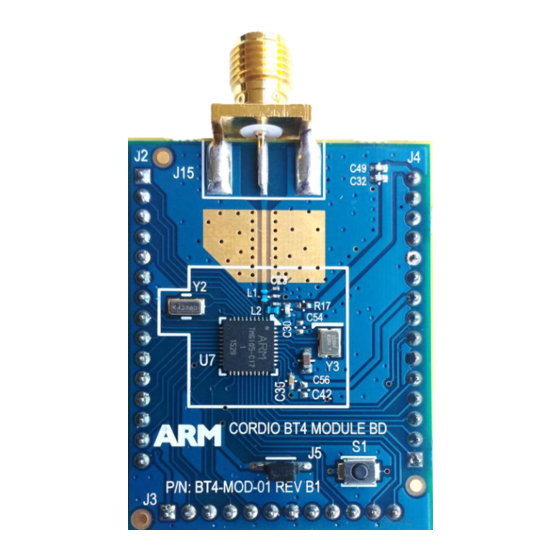
KIT CONTENTS Contents The CORDIO™ BT4 Evaluation and Development Kit contains the following items: ARM Cordio BT4 Module (P/N: Cordio BT4 Module BD) ARM Customer Evaluation Base Board (P/N: BT4-GEN2-EVAL) USB power cable USB to UART cable ... - Page 7 Figure 1.2 – Default Jumper and Switch Positions WH000 © Copyright ARM Limited 2016. All rights reserved. ARM-EPM-1017464.0 Confidential Page 2...
-
Page 8: Description
The Cordio BT4 Module and Customer Evaluation Base Board is based upon the CORDIO™ BT4 Development SoC which is a low power, 40 pin 5 x5 mm QFN that contains the BT4 Radio IP plus an ARM Cortex M0+™ host MCU. -
Page 9: Features
The board is mbed enabled allowing the user to utilize mbed tools and example source code as well as Keil tools to develop custom FW for their ARM Cortex based SoC while it is still in development. It also supports drag-n-drop FW programming of the Module. -
Page 10: Hardware
Figure 3.1 - BT4 Customer Evaluation Board – Block Diagram Block Diagram The ARM Cordio BT4 Radio IP can be run in either a 1 volt or 3 volt mode/domain. The Cortex M0 Host processor and its memories within the SoC are run at 1.2 volts. Level shifters are provided on all I/O buses to take the SPI and I2C interfaces to 1.8 Volts and the UART and Serial Wire Debug lines to 3.3v. -
Page 11: Power Selection And Switches
We recommend all 3 of these switches be slid to the right (towards the edge of the board) in the “OFF” positions so that the batteries are not drained due to powering their respective on-board voltage regulators. WH000 © Copyright ARM Limited 2016. All rights reserved. ARM-EPM-1017464.0 Confidential... -
Page 12: Battery Supplies
PLEASE NOTE: DO NOT SWITCH POWER MODES WHEN POWER IS SUPPLIED TO THE BOARD AS THIS MAY PERMENTANTLY DAMAGE THE SOC. Always power-down the board prior to moving this switch position! WH000 © Copyright ARM Limited 2016. All rights reserved. ARM-EPM-1017464.0 Confidential Page 7... -
Page 13: Power Domains
The table below shows the operational usage modes that are available in each of the 4 power source options. Table 3.2.3 - Power Source vs. Operation Mode WH000 © Copyright ARM Limited 2016. All rights reserved. ARM-EPM-1017464.0 Confidential Page 8... -
Page 14: Jumpers
The RCT has the ability to adjust both the 1 volt and 3 volt power rails to the BT4 Radio IP block within the SoC for various power consumption tests. Setting of the voltage level on either power rail is done by the RCT user interface. WH000 © Copyright ARM Limited 2016. All rights reserved. ARM-EPM-1017464.0 Confidential Page 9... -
Page 15: Current Measurement Jumpers
BT Radio IP Block is 1V_ADJ (J30) and 3V_ADJ (J31) as the other three LDO’s power additional devices on the board. Below is a description of what each voltage rail powers on the board. Table 3.3.2 - LDO Power Jumpers WH000 © Copyright ARM Limited 2016. All rights reserved. ARM-EPM-1017464.0 Confidential Page 10... -
Page 16: Uart/Swd Jumpers
USB connector. This is the default position that is used in most applications. This position allows serial communications with Test equipment and PCs running ARM’s Radio Control Tool via J14. Please note that the UART supports 3.3 volt signal level. A USB to UART cable is provided in the Kit that supports 3.3 volt signal level. -
Page 17: Headers
3.3 volt signal level. If you are connecting the Eval board to the RS-232 port of test equipment, you will need to install a signal level shifting cable or adapter! WH000 © Copyright ARM Limited 2016. All rights reserved. ARM-EPM-1017464.0 Confidential... -
Page 18: Volt Test Pins
The J17 header can be found just under the BT4 module in the upper center of the board. It provides access to the SPI bus of the BT4 Development SoC for use with external devices. WH000 © Copyright ARM Limited 2016. All rights reserved. ARM-EPM-1017464.0 Confidential... -
Page 19: Buttons
Red button on the base platform board. It is always a good idea to press either Reset button after power has been applied to the Evaluation Board. WH000 © Copyright ARM Limited 2016. All rights reserved. ARM-EPM-1017464.0 Confidential Page 14... -
Page 20: Wake-Up/Discoverable Button
Demonstration SoC. Under normal operation, this button will not be used. If pressed, it may momentarily interrupt communication between the Customer Eval Board and the Radio Control Tool. WH000 © Copyright ARM Limited 2016. All rights reserved. ARM-EPM-1017464.0 Confidential Page 15... -
Page 21: Fw Modes
(Red arrow) places the board into Sensor mode. The position of the jumper on the top row is not relevant if the lower jumper is set to Test or “HCI” FW mode. WH000 © Copyright ARM Limited 2016. All rights reserved. ARM-EPM-1017464.0 Confidential... -
Page 22: Current Measurement
(located along the top right edge of the board) in the 1 volt mode by sliding the switch upwards. (See Section 3.2.33.2). With power still removed from the board, remove the jumper from J30 (located just above the ARM mbed logo). Attach your desired current measuring equipment across the two lower pins of the connector as shown below. The center pin, Pin 2 on the connector, is the downstream voltage supply rail to the BT4 SoC. - Page 23 3 Tx events. For more information on this connectable or “discoverable” stateplease refer to Section 3.5.2. This type of measurement can also be taken in 3 volt mode as described in the next section. WH000 © Copyright ARM Limited 2016. All rights reserved. ARM-EPM-1017464.0 Confidential...
-
Page 24: Volt Mode - Current Measurement
3 volt mode by sliding the switch downwards. (See Section 3.2.3). With power still removed from the board, remove the jumper from J31 (located just above the ARM mbed logo). Attach your desired current measuring equipment across the two lower pins of the connector as shown below. The center pin, Pin 2 on the connector, is the downstream voltage supply rail to the BT4 SoC. -
Page 25: Test Mode
The common test set-up is depicted in the figure below. The DUT/EUT is controlled via the UART interface while RF measurements are received via a calibrated RF Coax cable, typically with an in-line 10db attenuator. Figure 6.1.1 – Bluetooth Analyzer Set-up WH000 © Copyright ARM Limited 2016. All rights reserved. ARM-EPM-1017464.0 Confidential Page 20... -
Page 26: Use Of Other Rf Analyzers
6.1.2 Use of other RF Analyzers As an alternate test method, ARM provides a Windows based Radio Control Tool, or “RCT” included in the BT4 Evaluation Kit. (See Section 6.1.3 below). The typical set-up for the RCT is depicted in the figure below. The PC is attached to the DUT (BT4 Eval Board) via a USB to UART cable as well as the USB to Mini-B USB cable, both provided in the kit. -
Page 27: Arm Radio Control Tool
6.1.3 ARM Radio Control Tool ARM’s Radio Control Tool (RCT) is a Windows/LabVIEW based utility that controls the BT4 Radio IP block via the BT4 Demonstration SoC’s Host UART port (J14). The tool can place the Radio in either continuous transmit mode or receive mode. -
Page 28: Regulatory Testing
Antenna as depicted below. This configuration can also be used for subjective range testing as well as during functional test during final end-product manufacturing and assembly. LabVIEW source code is available upon request from ARM for manufacturing test development. Figure 6.1.4 – Regulatory Testing Configuration WH000 ©... -
Page 29: Cmsis Dap Support
Additional information as well as the required Windows serial driver needed to communicate with the Evalution board can be found at the following links: https://developer.mbed.org/handbook/Windows-serial-configuration https://developer.mbed.org/handbook/CMSIS-DAP-MDK http://www2.keil.com/mdk5/install/ WH000 © Copyright ARM Limited 2016. All rights reserved. ARM-EPM-1017464.0 Confidential Page 24... -
Page 30: Demonstration Modes And Instructions
Check the box next to “Unknown Sources”. This allows installation of applications from both trusted and unknown sources. Move the ARM application to the phone/tablet (.apk file). This is easily done by just emailing it to an account that is accessible on the phone or tablet. ... -
Page 31: Demo And Fw Mode Jumper Selection
J19. Towards the right is the Sensor demo, towards the left is the UriBeacon demo. This will determine which operation mode is loaded at boot time (or Reset). WH000 © Copyright ARM Limited 2016. All rights reserved. ARM-EPM-1017464.0 Confidential Page 26... -
Page 32: Running Demos
“Power Mode Switch” to the “LINE” mode. 1. Open the ARM BT4 Browser Application on the phone or tablet. This App is required to be used for the Sensor demonstration. It can also be used for the Beacon Demonstration but you may find that use of the Google UriBeacon App is more useful. -
Page 33: Sensor Demo Screens
8.3.1 Sensor Demo Screens: 8.3.2 Beacon Demo Screens: WH000 © Copyright ARM Limited 2016. All rights reserved. ARM-EPM-1017464.0 Confidential Page 28... -
Page 34: Changing Between Demo Modes
Android Task Manager to shut down the application since it might be running in the background even though you appear to have closed it. WH000 © Copyright ARM Limited 2016. All rights reserved. ARM-EPM-1017464.0 Confidential... -
Page 35: Fw Update Procedure
FW UPDATE PROCEDURE Firmware updates may be periodically supplied by ARM. This procedure describes how to update firmware for the BT4 Demonstration SoC via the drag-n-drop programming capabilities provided by the on-board mbed controller. If you are using the BT4 Eval board as a code development platform you can use this same procedure to update the boards with your custom firmware. -
Page 36: Schematics And Boms
Schematics and the Bill of Materials (BOM) for both the Cordio BT4 Module and the Customer Evaluation Base board can be found in the Evaluation Board Schematics Document which should have been provided in the Evaluation and Demonstration Kit’s thumb drive. WH000 © Copyright ARM Limited 2016. All rights reserved. ARM-EPM-1017464.0 Confidential Page 31...
Need help?
Do you have a question about the Cordio BT4 Radio IP and is the answer not in the manual?
Questions and answers