CORNING Centrix Instructions Manual
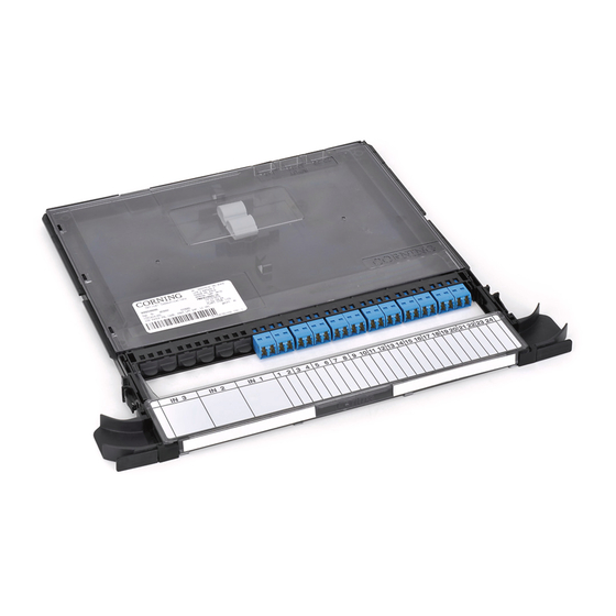
Patch panel cassette
Hide thumbs
Also See for Centrix:
- Manual (37 pages) ,
- Jumper routing (20 pages) ,
- Installation instruction (16 pages)
Table of Contents
Advertisement
Quick Links
Centrix™ System Patch Panel Cassette
P/N 003-1017-AEN
Issue 2
related literature | Search www.corning.com/opcomm. Click on "Resources."
003-948
1.
General
This document describes the installation of the Centrix™ System patch panel cassette into both rear- and front-
access Centrix System frames, 19-in racks, and 23-in frames. The 4U housing is shown in this instruction, but the
procedure applies to Centrix System housings of all sizes (1U, 2U, and 4U).
It is assumed that the Centrix housing has already been installed into the rack/frame according to the instructions
provided with the housing.
2.
Carton Contents
• Patch panel cassette
• Right-hand jumper routing waterfall and retainer clip kit (P/N CTX-KIT-RT-DH)
3.
Tools and Materials
• (Optional) Strain-relief bracket (P/N CTX-KIT-SR-SA)
4.
Installation of Rear-Access Cassettes into Rear-Access Frame
Rear-access cassettes can be installed into Centrix rear-access frames, 19-in racks, and 23-in frames.
Step 1:
Take note of the locations etched into the cover for the jumper inputs (Figure 1). Open the cover.
Step 2:
Feed the input jumpers into the cutouts in the back of the cassette in groups of 12 according to the
number of jumpers being installed - up to 24 SC connectors or 36 LC connectors. For example, install
jumpers 1-12 into the first cutout on the right, as viewed from the back of the cassette.
3
2
1
TPA-5490
Instruction, Centrix™ System Housing Installation
Standard Recommended Procedure 003-1017-AEN | Issue 2 | April 2017 | Page 1 of 8
Figure 1
Advertisement
Table of Contents

Related Manuals for CORNING Centrix


Summary of Contents for CORNING Centrix
- Page 1 This document describes the installation of the Centrix™ System patch panel cassette into both rear- and front- access Centrix System frames, 19-in racks, and 23-in frames. The 4U housing is shown in this instruction, but the procedure applies to Centrix System housings of all sizes (1U, 2U, and 4U).
- Page 2 Step 3: Pass the first 12 jumpers through the first guide (Figure 2). Step 4: Remove dust caps from the rear of the adapters and from the connectors. Clean the connector end faces and adapters per standard company practices or as described in Section 7. Step 5: Insert the connectors into the rear of the first 12 adapters.
- Page 3 Installation of Front-Access Cassettes in Front-Access Frame Front-Access Cassettes with Left-Hand Input Jumper Feed Front-access cassettes with left-hand input jumper feed can be installed into front-access Centrix frames, 19-in racks, and 23-in frames. Install the jumpers into the front-access cassettes, following the numbering scheme on the drop handle label (Figure 5).
- Page 4 Step 2: Open the cover of the cassette. Step 3: Remove the appropriate number of plugs from the input area. Step 4: Feed one end of each jumper through the opening in the front of the cassette (Figure 8). In a 24-port cassette, install eight jumpers per input.
- Page 5 Front-Access Cassettes with Right-Hand Input Jumper Feed Front-access cassettes with right-hand input jumper feed can only be installed into 19-in racks and 23-in frames, not into a Centrix frame. Install the jumpers into the front-access cassettes, following the numbering scheme on the drop handle label (Figure 10).
- Page 6 Step 6: Insert the connectors into the rear of the adapters. TPA-5484 Figure 13 Step 7: Once all jumpers have been installed into the cassette, slide the cassette into the housing, starting at the top. Step 8: Continue loading cassettes from the top to the bottom of the housing until it is full. TPA-5496 Figure 14 Standard Recommended Procedure 003-1017-AEN | Issue 2 | April 2017 | Page 6 of 8...
- Page 7 Raise handle. Dress jumper cords to the side of the cassette (Figure 16 right). • In a Centrix™ System frame, jumpers must route out the left side of the cassette. • In a 19-in rack or a 23-in frame, jumpers may route to the left, to the right, or in both directions. If routing jumpers out the right-hand side of the cassette, install the optional right-hand waterfall kit (CTX-KIT-RT-DH) as shown in Figure 6.
- Page 8 800-743-2675 • FAX: 828-325-5060 • International: +1-828-901-5000 • www.corning.com/opcomm Corning Optical Communications reserves the right to improve, enhance, and modify the features and specifications of Corning Optical Communications products without prior notification. A complete listing of the trademarks of Corning Optical Communications is available at www.corning.com/opcomm/trademarks. All other trademarks are the properties of their respective owners.
Need help?
Do you have a question about the Centrix and is the answer not in the manual?
Questions and answers