
Related Manuals for MSTRONIC PSE-SW5G-25 4 Series


Summary of Contents for MSTRONIC PSE-SW5G-25 4 Series
- Page 1 PSE-SW5G-25x4 5 Port PoE Switch & Extender (Repeat Ethernet and PoE) USER’S MANUAL MSTRONIC CO., LTD.
-
Page 2: Table Of Contents
User’s Manual PSE-SW5G series 1. General Information.............. 2. Hardware Description............LED Indicators..................Power Wiring ..................Ethernet Port Wiring................PD Port Wiring..................Network Application……………………………………......3. Technical Specification............MSTRONIC CO., LTD. -
Page 3: General Information
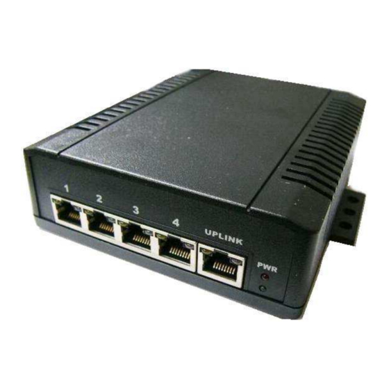
2. Hardware Description *LED Indicator There are 12 LEDs on the PoE switch to indicate the status of power and signal. The following section describes the functions of each LED indicator. Front panel detail MSTRONIC CO., LTD. - Page 4 10Mbps or 100Mbps. No device is detected. *PoE LED (the left indicator on RJ45) P1~P4 Yellow A valid Powered Device (PD) is detected and delivering power on this port. No PD is detected on this port. MSTRONIC CO., LTD.
-
Page 5: Power Wiring
If powered on port 5 (UPLINK) as a PoE repeater, the PoE input must be 44~57VDC, the input current is not over 2Amp. If powered via the rear terminal, please make sure the input current is not over 10A. MSTRONIC CO., LTD. - Page 6 * Data pair A plus V+ /V- on line 1 and 2 * Data pair B plus V-/V+ on line 3 and 6 * Data pair C plus V+/V- on line 4 and 5 * Data pair D plus V-/V+ on line 7 and 8 MSTRONIC CO., LTD.
-
Page 7: Ethernet Port Wiring
4 pairs or 2 pairs Ethernet cable. The following tables describe the wiring diagram of straight-through and crossover cabling. The crossover cables simply cross-connect the transmit lines at each end to the receive lines at the opposite end. MSTRONIC CO., LTD. - Page 8 If a port LED is off, go back and check for connectivity problems between that port and the network device connected. The maximum cable length for 10/100/1000BaseT with Cat 5 twisted pair cables is typically 100m (328 ft.). MSTRONIC CO., LTD.
-
Page 9: Pd Port Wiring
DC power to the PD. The yellow PoE LED will light up when the cable is correctly connected. Refer to the LED Indicator section for descriptions of each LED indicator. If a port LED is off, go back and check for connectivity problems between that port and the network device connected. MSTRONIC CO., LTD. -
Page 10: Network Application
IEEE 802.3af/at standard in the network. The PoE Switch can be installed in a more appropriate position for better performance to extend Ethernet to 200 meters. The following figure is an example of a network application for the PoE Switch. MSTRONIC CO., LTD. -
Page 11: Technical Specification
Pin assignment: *A mode: data pair A plus V+(1,2), data pair B plus V-(3,6), data pair C(4,5), data pair (7,8) *B mode: data pair A(1,2), data pair B(3,6), data pair C plus V+(4,5), data pair D plus V-(7,8) MSTRONIC CO., LTD. - Page 12 Power input PoE source on Port 5 (UPLINK), and/or optional DC power supply on rear terminal. Power consumption less than 5W when without PD loading Input PSE-SW5G25x4 0.340A 0.170A Power efficiency 85% at full load (@48V typical) MSTRONIC CO., LTD.
- Page 13 <3pF (VR = 0V, f = 1MHz, I/O pin to GND) Max. Shut Capacitance < 1.5 pF (VR = 0V, f = 1MHz, Between I/O pins) IEC61000-4-2 (ESD) ±15kV (air), ±8kV (contact) IEC COMPATIBILITY (EN61000-4) IEC61000-4-4 (EFT) 40A (5/50ns) IEC61000-4-5 (Lightning) 20A (8/20µs) MSTRONIC CO., LTD.
Need help?
Do you have a question about the PSE-SW5G-25 4 Series and is the answer not in the manual?
Questions and answers