KaVo ELECTROmatic TM Instructions For Use Manual
Hide thumbs
Also See for ELECTROmatic TM:
- Instructions for use manual (80 pages) ,
- Instructions for use manual (90 pages)

Related Manuals for KaVo ELECTROmatic TM


Summary of Contents for KaVo ELECTROmatic TM
- Page 1 Instructions for use ELECTROmatic TM and TMM/TMC as of panel software version V1.4...
- Page 2 Distributed by: Manufactured by: KaVo Dental Technologies, LLC KaVo Dental GmbH 11727 Fruehauf Drive Bismarckring 39 Charlotte, NC 28273 USA 88400 Biberach Phone: 847 550 6800 Germany Fax: 847 550 6825 www.kavo.com...
-
Page 3: Table Of Contents
Instructions for use ELECTROmatic TM and TMM/TMC as of panel software version V1.4 Table of contents Table of contents 1 User notes........................... 6 1.1 User guidelines......................6 1.1.1 Abbreviations..................... 1.1.2 General marks and symbols ................1.2 Target group ......................... 7 1.3 Service ......................... - Page 4 Instructions for use ELECTROmatic TM and TMM/TMC as of panel software version V1.4 Table of contents 4.7.3 Mount control panel on the side of a holder............45 4.7.4 Mount control panel to cabinet/wall..............47 4.8 Connecting the ELECTROmatic ..................48 4.9 Check the installation.....................
- Page 5 Instructions for use ELECTROmatic TM and TMM/TMC as of panel software version V1.4 Table of contents 8.5 Storage ........................78 8.6 Service, inspection and testing after processing ..............78 9 Maintenance ........................79 9.1 Changing the filter - water inlet..................79 9.2 Replacing the motor hose ....................
-
Page 6: User Notes
Instructions for use ELECTROmatic TM and TMM/TMC as of panel software version V1.4 1 User notes | 1.1 User guidelines 1 User notes 1.1 User guidelines Requirement Read these instructions prior to first startup to avoid misuse and prevent dam- age. -
Page 7: Target Group
Instructions for use ELECTROmatic TM and TMM/TMC as of panel software version V1.4 1 User notes | 1.2 Target group Hazard levels The warning and safety notes in this document must be observed to prevent personal injury and property damage. The warning notes are designated as... -
Page 8: Repair Service
Instructions for use ELECTROmatic TM and TMM/TMC as of panel software version V1.4 1 User notes | 1.4 Warranty terms and conditions 1.3.1 Repair Service For repairs, please contact KaVo Repair Service. For scheduling or if you have any questions, please contact:... -
Page 9: Information On The Packaging: Storage And Transport
Instructions for use ELECTROmatic TM and TMM/TMC as of panel software version V1.4 1 User notes | 1.5 Transportation and storage 5. Report the damage to KaVo. 6. Consult with KaVo first, before returning a damaged product. 7. Send the signed delivery receipt to KaVo. - Page 10 Instructions for use ELECTROmatic TM and TMM/TMC as of panel software version V1.4 1 User notes | 1.5 Transportation and storage Caution Follow instructions for use Follow the electronic instructions for use HIBC Code CE mark (European Conformity mark) VDE mark MET mark EAC conformity mark (Eurasian Conformity = Eurasische Konformität)
-
Page 11: Disposal
Instructions for use ELECTROmatic TM and TMM/TMC as of panel software version V1.4 1 User notes | 1.6 Disposal Humidity Do not dispose of this product in the ordinary municipal waste or garbage system 1.6 Disposal Note Any waste produced must be recycled or disposed of in strict compliance with all applicable national regulations in a manner which is safe for both people and the environment. -
Page 12: Safety
Instructions for use ELECTROmatic TM and TMM/TMC as of panel software version V1.4 2 Safety | 2.1 Infection hazard 2 Safety Note All serious events occurring in relation to the product must be reported to the manufacturer and the competent authority of the member state, in which the user and/or patient resides. -
Page 13: Ingress Of Liquids
Instructions for use ELECTROmatic TM and TMM/TMC as of panel software version V1.4 2 Safety | 2.4 Ingress of liquids ▶ Power supply and cord/hoses need to be set-up/routed appropriately such that they are not on the floor. Note The SAFEdrive function is a monitoring function for detection of defective high-speed handpieces. -
Page 14: Electromagnetic Fields
Instructions for use ELECTROmatic TM and TMM/TMC as of panel software version V1.4 2 Safety | 2.8 Electromagnetic fields Repairs and safety checks may only be performed by trained service personnel. The following persons are authorized to do this: ▪ Service technicians of KaVo branches after the appropriate product training ▪... -
Page 15: Product Description
Instructions for use ELECTROmatic TM and TMM/TMC as of panel software version V1.4 3 Product description | 3.1 Purpose - proper use 3 Product description The ELECTROmatic dental control unit is a stand-alone system for operating electric driven handpieces. An external power supply provides electric power to the unit. - Page 16 Instructions for use ELECTROmatic TM and TMM/TMC as of panel software version V1.4 3 Product description | 3.1 Purpose - proper use Definition (purpose) Explanation Specification of the primary function Network-dependent add-on devise for the dentist unit Duration of use...
-
Page 17: Scope Of Delivery
Instructions for use ELECTROmatic TM and TMM/TMC as of panel software version V1.4 3 Product description | 3.2 Scope of delivery 3.2 Scope of delivery Figure Catalog num- ELECTROmatic TM ELECTROmatic TMM/TMC ELECTROmatic ELECTROmatic ELECTROmatic Control unit 1.011.2100 Control unit 1.011.2600... - Page 18 Instructions for use ELECTROmatic TM and TMM/TMC as of panel software version V1.4 3 Product description | 3.2 Scope of delivery Figure Catalog num- ELECTROmatic TM ELECTROmatic TMM/TMC ELECTROmatic ELECTROmatic ELECTROmatic 1.007.0150 INTRA LUX Motor KL 703 LED KL Motor hose 1750 1.011.7200...
- Page 19 Instructions for use ELECTROmatic TM and TMM/TMC as of panel software version V1.4 3 Product description | 3.2 Scope of delivery Figure Catalog num- ELECTROmatic TM ELECTROmatic TMM/TMC ELECTROmatic ELECTROmatic ELECTROmatic Assembly instructions 1.013.0312 CAUTION Use of un-authorized accessories on the device or un-authorized modifications to the device can lead to injury.
- Page 20 Instructions for use ELECTROmatic TM and TMM/TMC as of panel software version V1.4 3 Product description | 3.2 Scope of delivery ELECTROmatic installation set (Mat. no. 1.012.1883) Pos. Mat. No. Description Number 0.251.5804 Hexagonal nuts M4 ① 0.242.4012 Washers ②...
-
Page 21: Electromatic - Versions
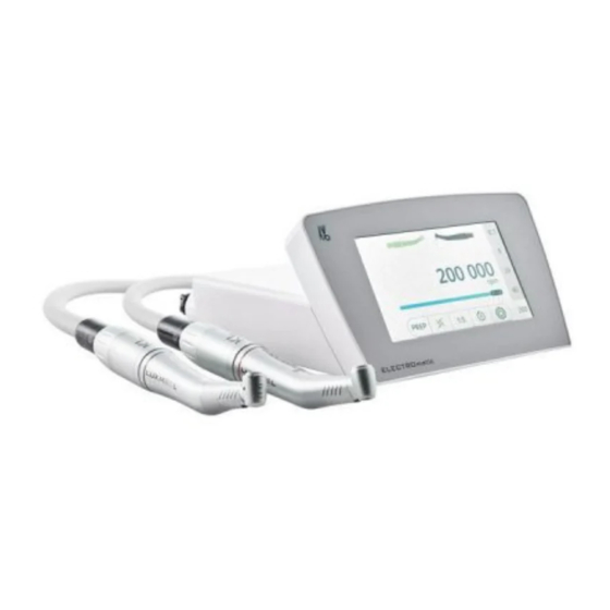
Instructions for use ELECTROmatic TM and TMM/TMC as of panel software version V1.4 3 Product description | 3.3 ELECTROmatic – Versions 3.3 ELECTROmatic – Versions ELECTROmatic TM ELECTROmatic TMM/TMC ELECTROmatic Front and rear of the device ① Control panel ⑤ Motor hose connector:... -
Page 22: Motor Hose
Instructions for use ELECTROmatic TM and TMM/TMC as of panel software version V1.4 3 Product description | 3.4 Motor hose 3.4 Motor hose KL motor hose/COMFORTbase ① Connector for ELECTROmatic ④ Connector for motor ② KL motor hose 1750/2200 / ⑤... - Page 23 Instructions for use ELECTROmatic TM and TMM/TMC as of panel software version V1.4 3 Product description | 3.5 Control panel Control element Name/type of control Function element Toggle switch ▶ Press the toggle switch for 2 seconds ▪ "SETUP", Device set- to start "SETUP", De-...
- Page 24 Instructions for use ELECTROmatic TM and TMM/TMC as of panel software version V1.4 3 Product description | 3.5 Control panel Control element Name/type of control Function element Toggle switch "Lock" Lock is locked (by de- fault) ▶ Press the "Lock" con-...
- Page 25 Instructions for use ELECTROmatic TM and TMM/TMC as of panel software version V1.4 3 Product description | 3.5 Control panel Pos. Description active/deactivated Presentation ⑥ Toggle switch "Direc- Counterclockwise rota- tion of motor rotation" tion is active An audible message is...
- Page 26 Instructions for use ELECTROmatic TM and TMM/TMC as of panel software version V1.4 3 Product description | 3.5 Control panel Pos. Description active/deactivated Presentation ⑦ Toggle switch SAFEdrive is active blue background "SAFEdrive" Toggle switch PREP mode is active ⑧...
-
Page 27: Technical Specifications Of The Electromatic
Instructions for use ELECTROmatic TM and TMM/TMC as of panel software version V1.4 3 Product description | 3.6 Technical specifications of the ELECTROmatic Pos. Description active/deactivated Presentation ⑤ Slider with Plus/Minus Speed is active = ap- control keys for speed/ prox. - Page 28 Instructions for use ELECTROmatic TM and TMM/TMC as of panel software version V1.4 3 Product description | 3.6 Technical specifications of the ELECTROmatic Dimensions and weight of the control unit Width 150 mm / 5.90" Depth 135 mm / 5.31"...
- Page 29 Instructions for use ELECTROmatic TM and TMM/TMC as of panel software version V1.4 3 Product description | 3.6 Technical specifications of the ELECTROmatic Note If a handpiece is defective, the treatment time might be less than 30 seconds due to the SAFEdrive function (automatic motor shut-off).
-
Page 30: Symbols On Product And Rating Plate
Instructions for use ELECTROmatic TM and TMM/TMC as of panel software version V1.4 3 Product description | 3.7 Symbols on product and rating plate Electrical ratings Input voltage 36 V DC Power 120 W Motor cords Cable lengths, 1.75 m / 2.20 m (69" / 87") depends on ordered version| 3.7 Symbols on product and rating plate... -
Page 31: Power Supply Type 4882
Instructions for use ELECTROmatic TM and TMM/TMC as of panel software version V1.4 3 Product description | 3.8 Power supply type 4882 Type B applied part Supply voltage Operating mode: continuous operation with intermittent load Protection class II Do not dispose of with household waste 3.8 Power supply type 4882... -
Page 32: Symbols On The Nameplate Of The Type 4882 Power Supply
Instructions for use ELECTROmatic TM and TMM/TMC as of panel software version V1.4 3 Product description | 3.10 Symbols on the nameplate of the type 4882 power supply Dimensions and weight Width 160 mm/6.3 " Height 44 mm/1.7 " Depth 76 mm/3 "... - Page 33 Instructions for use ELECTROmatic TM and TMM/TMC as of panel software version V1.4 3 Product description | 3.10 Symbols on the nameplate of the type 4882 power supply Certification TÜV Rheinland mark UL mark for components for USA/Canada CE mark...
-
Page 34: Installation
Instructions for use ELECTROmatic TM and TMM/TMC as of panel software version V1.4 4 Installation | 4.1 Location 4 Installation WARNING Electrical sparks in the product can lead to explosion or fire. ▶ Do not use the product in explosion hazard areas. -
Page 35: Installation Positions
Instructions for use ELECTROmatic TM and TMM/TMC as of panel software version V1.4 4 Installation | 4.2 Installation positions 4.2 Installation positions There is a wide range of installation options for the ELECTROmatic. This over- view makes no claim of being comprehensive. If possible, the installation should be done without modification of the dentist element and/or existing at- tachment options on the dentist element should be utilized. -
Page 36: Preparing The Installation
Instructions for use ELECTROmatic TM and TMM/TMC as of panel software version V1.4 4 Installation | 4.3 Preparing the installation 4.3 Preparing the installation Insert holder Mounting plate ELECTROmatic installation set (Mat. no. 1.012.1883) Mounting bracket Cover panel ▶ Keep the installation set handy. - Page 37 Instructions for use ELECTROmatic TM and TMM/TMC as of panel software version V1.4 4 Installation | 4.4 Installation position 1: Mount below a holder CAUTION Damage to the dentist element. Installations involving an intervention on the dental unit might damage compo- nents, which can interfere with the safe function and cause injury.
-
Page 38: Installation Position 2: Mount On The Side Of A Holder
Instructions for use ELECTROmatic TM and TMM/TMC as of panel software version V1.4 4 Installation | 4.5 Installation position 2: Mount on the side of a holder Installation variant c) The following parts from the scope of delivery and the installation set are re- quired: ▪... - Page 39 Instructions for use ELECTROmatic TM and TMM/TMC as of panel software version V1.4 4 Installation | 4.5 Installation position 2: Mount on the side of a holder ▪ 4x Washers ② ▪ 2x Plastic screws ⑥ for fastening to the mounting plate ▶...
-
Page 40: Installation Position 3: Mount On A Holder Or On The Backside Of A Holder
Instructions for use ELECTROmatic TM and TMM/TMC as of panel software version V1.4 4 Installation | 4.6 Installation position 3: Mount on a holder or on the backside of a holder 4.6 Installation position 3: Mount on a holder or on the... - Page 41 Instructions for use ELECTROmatic TM and TMM/TMC as of panel software version V1.4 4 Installation | 4.6 Installation position 3: Mount on a holder or on the backside of a holder Installation variant b) The following parts from the scope of delivery and the installation set are re- quired: ▪...
-
Page 42: Installation Position 4: Mount Control Panel As Remote Control
Instructions for use ELECTROmatic TM and TMM/TMC as of panel software version V1.4 4 Installation | 4.7 Installation position 4: Mount control panel as remote control 4.7 Installation position 4: Mount control panel as remote control 4.7.1 Disconnect the control panel from the control unit and install it on the mounting bracket ▶... - Page 43 Instructions for use ELECTROmatic TM and TMM/TMC as of panel software version V1.4 4 Installation | 4.7 Installation position 4: Mount control panel as remote control ▶ If required, break out the cable feed-through on the control panel. ▶ Guide the connecting cable of the control unit through this opening to the control panel.
-
Page 44: Mount Control Panel On A Holder / On The Backside Of A Holder
Instructions for use ELECTROmatic TM and TMM/TMC as of panel software version V1.4 4 Installation | 4.7 Installation position 4: Mount control panel as remote control 4.7.2 Mount control panel on a holder / on the backside of a holder CAUTION Damage to the dentist element. -
Page 45: Mount Control Panel On The Side Of A Holder
Instructions for use ELECTROmatic TM and TMM/TMC as of panel software version V1.4 4 Installation | 4.7 Installation position 4: Mount control panel as remote control ▶ Mount the control unit. See also: 2 4.4 Install below the dentist element, a holder or a cabinet, Page 36 4.7.3 Mount control panel on the side of a holder... - Page 46 Instructions for use ELECTROmatic TM and TMM/TMC as of panel software version V1.4 4 Installation | 4.7 Installation position 4: Mount control panel as remote control ▶ Mark the attachment points and drill the holes on the holder. ▶ Screw the mounting bracket with control panel to the round side of the mounting plate using the plastic screws ⑥...
-
Page 47: Mount Control Panel To Cabinet/Wall
Instructions for use ELECTROmatic TM and TMM/TMC as of panel software version V1.4 4 Installation | 4.7 Installation position 4: Mount control panel as remote control ▶ Mark the attachment points and drill the holes. ▶ Use the 2 screws ④ and the washers ② to screw the mounting bracket with control panel to the holder and secure it with the nuts ①. -
Page 48: Connecting The Electromatic
Instructions for use ELECTROmatic TM and TMM/TMC as of panel software version V1.4 4 Installation | 4.8 Connecting the ELECTROmatic CAUTION Damage to the dentist element. Installations involving an intervention on the dental unit might damage compo- nents, which can interfere with the safe function and cause injury. -
Page 49: Commissioning
Instructions for use ELECTROmatic TM and TMM/TMC as of panel software version V1.4 5 Commissioning | 5.1 Connection 5 Commissioning WARNING Electrical shock. Electrically conductive environments may cause electric shock. ▶ Use the product only in environments that are not electrically conductive. -
Page 50: Connecting The Electromatic
Instructions for use ELECTROmatic TM and TMM/TMC as of panel software version V1.4 5 Commissioning | 5.1 Connection Air and water requirements according to DIN EN 7494-2 The compressed air must be free of oil, dirt, and contamination. If needed: ▪... -
Page 51: Connecting The Motor
Instructions for use ELECTROmatic TM and TMM/TMC as of panel software version V1.4 5 Commissioning | 5.1 Connection 5.1.3 Connecting the motor ▶ Slightly wet the O-rings on the connection hose with KAVOspray. ▶ Connect the motor to the supply hose and twist. -
Page 52: Calibrating The Foot Control
Instructions for use ELECTROmatic TM and TMM/TMC as of panel software version V1.4 5 Commissioning | 5.2 Calibrating the foot control Note The connection of the power supply must comply with the country-specific regulations and requirements for medical devices. Note The power supply automatically adjusts to the available mains voltage. -
Page 53: Measure Cooling Air Quantity At Motor Coupling
Instructions for use ELECTROmatic TM and TMM/TMC as of panel software version V1.4 5 Commissioning | 5.3 Measure cooling air quantity at motor coupling 5.3 Measure cooling air quantity at motor coupling ▶ Place the airflow measuring tube ① (Mat. no. 0.411.4441) on the motor. - Page 54 Instructions for use ELECTROmatic TM and TMM/TMC as of panel software version V1.4 5 Commissioning | 5.4 Making the device settings ▶ Press the arrow control keys to select the various parameters. ▶ Press the Plus control element to increase a value.
- Page 55 Instructions for use ELECTROmatic TM and TMM/TMC as of panel software version V1.4 5 Commissioning | 5.4 Making the device settings Display information Setting The volume of the tone when you touch a control el- ement can be adjusted between 1 and 3.
-
Page 56: Operation
Instructions for use ELECTROmatic TM and TMM/TMC as of panel software version V1.4 6 Operation | 5.4 Making the device settings 6 Operation WARNING Electrical shock. A damaged product or damaged components may cause electric shock. ▶ Use the device and components only if there is no damage on the outside. -
Page 57: Switching The Electromatic On/Off
Instructions for use ELECTROmatic TM and TMM/TMC as of panel software version V1.4 6 Operation | 6.1 Switching the ELECTROmatic on/off NOTICE Contaminated or moist compressed air at the compressed air connec- tion. Premature wear. ▶ Supply dry, clean and uncontaminated compressed air in accordance with ISO 7494-2 only. -
Page 58: Regulating The Spray Water
Instructions for use ELECTROmatic TM and TMM/TMC as of panel software version V1.4 6 Operation | 6.3 Regulating the spray water ▶ Press the foot control partly down in order to regulate the speed between minimum and maximum speed. 6.3 Regulating the spray water CAUTION Hazard from insufficient amount of spray water. - Page 59 Instructions for use ELECTROmatic TM and TMM/TMC as of panel software version V1.4 6 Operation | 6.4 PREP mode Speed display motor left Speed display motor right Speed display COMFORTdrive right The following factory settings a pre-selected as defaults for the speed memo-...
-
Page 60: Changing The Direction Of Rotation
Instructions for use ELECTROmatic TM and TMM/TMC as of panel software version V1.4 6 Operation | 6.4 PREP mode ▶ Select a transmission ratio from the selection list. Scroll the selection list up or down and select a transmission ratio. -
Page 61: Protection Function Safedrive
Instructions for use ELECTROmatic TM and TMM/TMC as of panel software version V1.4 6 Operation | 6.4 PREP mode 6.4.3 Protection function SAFEdrive WARNING Use of incorrect straight and contra-angle handpieces. Risk of burn injury or overheating. ▶ Use only original KaVo high-speed handpieces of the 25L, E25, M25, M05, 25LP, 25LPA, 25LPR, 25LCA series or the COMFORTdrive motorized contra- angle handpiece. - Page 62 Instructions for use ELECTROmatic TM and TMM/TMC as of panel software version V1.4 6 Operation | 6.4 PREP mode ▶ Press the "SAFEdrive" control element to activate or deactivate SAFEdrive for the active speed memory. ð SAFEdrive is active = Control element has a blue background.
-
Page 63: Endo Mode
Instructions for use ELECTROmatic TM and TMM/TMC as of panel software version V1.4 6 Operation | 6.5 ENDO mode ▶ The motor can be restarted if there is no damage or overheating evident. To do so, press the foot control again. -
Page 64: Using The Endo Mode
Instructions for use ELECTROmatic TM and TMM/TMC as of panel software version V1.4 6 Operation | 6.5 ENDO mode Note The INTRA LUX KL 703 LED motor has a torque range from 0.15 to 3 Ncm. If the torque exceeds 2.0 Ncm, KaVo recommends using a reducing contra-an- gle handpiece 3:1 or 8:1 in order to reduce the load on and heating of the motor. -
Page 65: File Database
Instructions for use ELECTROmatic TM and TMM/TMC as of panel software version V1.4 6 Operation | 6.5 ENDO mode ▶ Or press the Plus or Minus key to increase or decrease the activated value by individual steps. 6.5.2 File database ELECTROmatic TM and TMM/TMC possess an integrated file database. - Page 66 Instructions for use ELECTROmatic TM and TMM/TMC as of panel software version V1.4 6 Operation | 6.5 ENDO mode ð The display shows file sequence "SEQUENCE 1" in editing mode. ▶ Tap the "Pen" control element again to edit the sequence name.
- Page 67 Instructions for use ELECTROmatic TM and TMM/TMC as of panel software version V1.4 6 Operation | 6.5 ENDO mode If the set speed or torque differs from the recommended value of this file, a crossed-out factory symbol is shown. Changing the file position in the sequence...
- Page 68 Instructions for use ELECTROmatic TM and TMM/TMC as of panel software version V1.4 6 Operation | 6.5 ENDO mode ▶ Tap the "Pen" control element to edit the sequence. ð The display shows file sequence "SEQUENCE 1" in editing mode.
- Page 69 Instructions for use ELECTROmatic TM and TMM/TMC as of panel software version V1.4 6 Operation | 6.5 ENDO mode ▶ Open the file editor, then tap file sequence "SEQUENCE 1" to display the se- lection list of the file sequences.
- Page 70 Instructions for use ELECTROmatic TM and TMM/TMC as of panel software version V1.4 6 Operation | 6.5 ENDO mode Deactivating file from file sequence If the user does not need all 10 files of the file sequence for the treatment, he or she can deactivate files in the sequence.
-
Page 71: Selecting An Endo File Sequence
Instructions for use ELECTROmatic TM and TMM/TMC as of panel software version V1.4 6 Operation | 6.5 ENDO mode 6.5.4 Selecting an ENDO file sequence ▶ Select the ENDO file sequence using the "File sequence" selection list by pressing the desired file sequence (presently SEQUENCE 1). -
Page 72: Setting The Endo Torque
Instructions for use ELECTROmatic TM and TMM/TMC as of panel software version V1.4 6 Operation | 6.5 ENDO mode ▶ If the torque is active, activate the speed by touching the speed value. ▶ To change the speed pull the slider to the right or left. - Page 73 Instructions for use ELECTROmatic TM and TMM/TMC as of panel software version V1.4 6 Operation | 6.5 ENDO mode There are three different torque modes in ENDO mode: ▪ Torque Control ▪ Auto-reverse ▪ Autorev/Forward ▶ Tap the "Lock" control element to unlock settings.
- Page 74 Instructions for use ELECTROmatic TM and TMM/TMC as of panel software version V1.4 6 Operation | 6.5 ENDO mode Once 90% of the set torque value are reached, a notifying beep is issued and the light starts to pulse. Once the set torque is reached, the motor stops and then automatically starts at the same speed in counterclockwise direction.
-
Page 75: Decommissioning
Instructions for use ELECTROmatic TM and TMM/TMC as of panel software version V1.4 7 Decommissioning | 7.1 Disconnecting the electrical connection 7 Decommissioning WARNING Dispose of the product in the appropriate manner. Infection hazard. ▶ Process the product and accessories before disposal. -
Page 76: Processing Steps In Accordance With Din En Iso 17664
Instructions for use ELECTROmatic TM and TMM/TMC as of panel software version V1.4 8 Processing steps in accordance with DIN EN ISO 17664 | 8.1 Cleaning 8 Processing steps in accordance with DIN EN ISO 17664 WARNING Hazard from contaminated products. -
Page 77: Manual Cleaning Of The Inside
Instructions for use ELECTROmatic TM and TMM/TMC as of panel software version V1.4 8 Processing steps in accordance with DIN EN ISO 17664 | 8.2 Disinfection 8.1.3 Manual cleaning of the inside There is no specific cleaning of the inside of the unit. -
Page 78: Manual Disinfection Of The Interior
Instructions for use ELECTROmatic TM and TMM/TMC as of panel software version V1.4 8 Processing steps in accordance with DIN EN ISO 17664 | 8.3 Packaging Note Comply with the instructions for use of the disinfectant. 8.2.2 Manual disinfection of the interior The germ reduction of the ELECTROmatic must be carried out via the treatment unit. -
Page 79: Maintenance
Instructions for use ELECTROmatic TM and TMM/TMC as of panel software version V1.4 9 Maintenance | 9.1 Changing the filter - water inlet 9 Maintenance WARNING Electrical shock. Use the device and components only if there is no damage on the outside. -
Page 80: Replacing The Motor Hose
Instructions for use ELECTROmatic TM and TMM/TMC as of panel software version V1.4 9 Maintenance | 9.2 Replacing the motor hose ▶ Undo the union nut proceeding in the direction of the arrow. ▶ Replace the filter insert (Mat. no. 1.007.9736) ① if there is any visible soiling. -
Page 81: 10Troubleshooting
Instructions for use ELECTROmatic TM and TMM/TMC as of panel software version V1.4 10 Troubleshooting 10 Troubleshooting Note This product displays error messages and/or instructions visibly on its dis- play. The motor is shut off in any case of malfunction. - Page 82 Instructions for use ELECTROmatic TM and TMM/TMC as of panel software version V1.4 10 Troubleshooting Malfunction Cause Remedy ▶ Check/restore correct connection. Device malfunctions No voltage supply on ▶ Replace the connection cable to the control (no display, the LED on the control panel.
- Page 83 Instructions for use ELECTROmatic TM and TMM/TMC as of panel software version V1.4 10 Troubleshooting Malfunction Cause Remedy ▶ Confirm message and check or correct the pro- Event E8 Saved data or settings gram settings. have been reset to ▶ If error persists, notify the service engineer.
-
Page 84: 11Components And Miscellaneous
Instructions for use ELECTROmatic TM and TMM/TMC as of panel software version V1.4 11 Components and miscellaneous 11 Components and miscellaneous Components Description Material number Power supply 1.005.0120 KL Motor hose 2200 1.011.5668 COMFORTbase 2200 1.011.7076 KL Motor hose 1750 1.011.7200... -
Page 85: 12Information On Electromagnetic Compatibility
Instructions for use ELECTROmatic TM and TMM/TMC as of panel software version V1.4 12 Information on electromagnetic compatibility | 12.1 Guidelines and manufacturer's declaration - electromagnetic emission 12 Information on electromagnetic compatibility 12.1 Guidelines and manufacturer's declaration - electromagnetic emission The ELECTROmatic is intended for use in an environment of the kind specified below. -
Page 86: Guidelines And Manufacturer's Statement - Electromagnetic Immunity
Instructions for use ELECTROmatic TM and TMM/TMC as of panel software version V1.4 12 Information on electromagnetic compatibility | 12.3 Guidelines and manufacturer's statement - Electromagnetic immunity Interference immu- IEC 60601 test lev- Compliance level Electromagnetic environment nity tests - Guidelines Electrostatic discharge ±... - Page 87 Instructions for use ELECTROmatic TM and TMM/TMC as of panel software version V1.4 12 Information on electromagnetic compatibility | 12.3 Guidelines and manufacturer's statement - Electromagnetic immunity Interference immu- IEC 60601 test lev- Compliance level Electromagnetic environment nity tests - Guidelines...
-
Page 88: Recommended Safe Distances Between Portable And Mobile Hf Telecommunications Equipment And The Electromatic
Instructions for use ELECTROmatic TM and TMM/TMC as of panel software version V1.4 12 Information on electromagnetic compatibility | 12.4 Recommended safe distances between portable and mobile HF telecommunications equipment and the ELECTROmatic Comment 2: These guidelines may not be applicable in every case. The spread of electromagnetic waves is absorbed and reflected by buildings, objects and people.
Need help?
Do you have a question about the ELECTROmatic TM and is the answer not in the manual?
Questions and answers
Getting an E 22 code on my Electromatic hand piece. Repair person said it all looks good. Went to use it and it through the code need help