Table of Contents
Advertisement
Quick Links
Advertisement
Table of Contents

Related Manuals for KaVo ERGOcom 3


Summary of Contents for KaVo ERGOcom 3
- Page 1 Instructions for use ERGOcom 3 Always be on the safe side.
- Page 2 Sales: Manufacturer: KaVo Dental GmbH Kaltenbach & Voigt GmbH Bismarckring 39 Bismarckring 39 D-88400 Biberach D-88400 Biberach +49 7351 56-0 Fax +49 7351 56-1488...
-
Page 3: Table Of Contents
3.4 Rating plate ............................14 3.5 Technical data ............................15 4 Start-up ................................16 4.1 Start-up ..............................16 4.2 Setting up the RF receiver for ERGOcom 3 excellence .................17 4.2.1 Select channel ..........................17 4.2.2 Learn channel ..........................18 4.3 Connect PC ............................19 4.4 Setting up the ERGOcom 3 comfort/excellence USB drive ..............20 4.5 Installing own image as user logo ......................21... - Page 4 6 Preparation methods DIN EN ISO 17664 ....................46 6.1 Cleaning ..............................46 6.1.1 Exterior cleaning by hand ......................46 6.2 Disinfection ............................47 6.3 Maintenance ............................48 7 Safety checks ...............................49 8 Troubleshooting ............................50 8.1 ERGOcom 3 device manager list ......................51 9 Glossary ...............................54 2/54...
-
Page 5: User Notes
Instructions for use ERGOcom 3 1 User Notes 1.1 User guidelines 1 User Notes 1.1 User guidelines Requirement Please read these instructions before using the product to avoid operator error and damage. 1.1.1 Abbreviations Abbre‐ Meaning viation User instructions Care instructions... -
Page 6: Service
Instructions for use ERGOcom 3 1 User Notes 1.2 Service 1.2 Service Service hotline: +49 7531 56-2700 Service.Multimedia@kavo.com Please indicate the product serial number in all requests. Additional information can be obtained at: www.kavo.com 4/54... -
Page 7: Guarantee Provisions
As a general rule, this guarantee does not apply to lamps, glassware, rubber parts or the colour durability of synthetic materials. KaVo shall not be liable for defects or their consequences if they are likely to be a direct result of actions or modifications by a customer or third party. -
Page 8: Transportation And Storage
1.4.1 Packaging ordinance of August 28,1998 Note Applies only to the Federal Republic of Germany. KaVo transit packaging is disposed of and recycled by local waste management and recycling companies under Germany's Dual System. For more information about waste management and recycling, and for up-to-date lists of local waste management and recycling companies, visit the following sites: http://www.umweltdatenbank.de... -
Page 9: Storage
1 User Notes 1.4 Transportation and storage Outside of Germany Note KaVo shall not be liable for damage caused in transit. Check the shipment immediately upon delivery! If the outer packaging is noticeably damaged upon delivery, you must proceed as follows: 1. -
Page 10: Safety
Instructions for use ERGOcom 3 2 Safety 2.1 Description of safety instructions 2 Safety 2.1 Description of safety instructions 2.1.1 Warning symbol Warning symbol 2.1.2 Structure The introduction describes the type and source of the danger. This section portrays the possible consequences of non-observance. -
Page 11: Intended Purpose
The appropriate, comprehensive guidelines for this product and/or national laws, national regulations and technlogical rules for starting up and operating have to be applied and fulfilled in line with the specified, intended purpose of the KaVo product. Note Dispose of or recycle the waste materials produced without endangering human health or the environment and under observance of the applicable national regu‐... -
Page 12: Safety Instructions
CAUTION ▶ Consult the patient before treatment! The KaVo product is not permitted to be used in areas subject an explosion hazard. The following individuals are authorised to repair and maintain the KaVo product: ▪ Service Technicians from KaVo offices. -
Page 13: Product Description
3.1 Product name Note These user instructions apply to ERGOcom 3, from serial number 1000723. ERGOcom 3 is available in three different designs: classic, comfort and excellence. These models differ from one another in terms of their in-built components. Model... -
Page 14: Controls
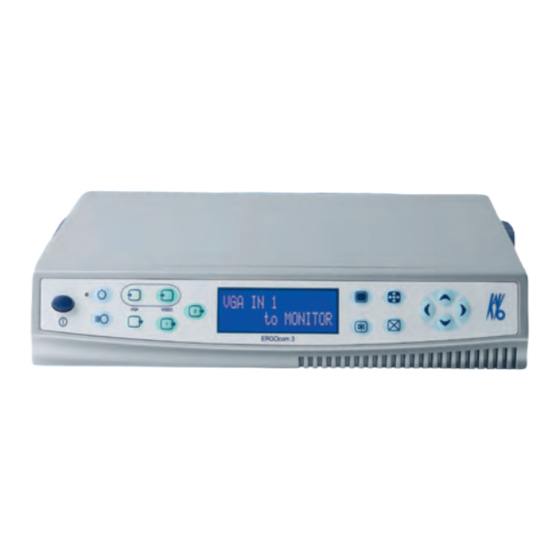
Instructions for use ERGOcom 3 3 Product description 3.2 Controls 3.2 Controls ① Main switch ⑩ Navigation up ② Standby LED, blue ⑪ Navigation right ③ Standby ⑫ Navigation down ④ VGA IN 1/VGA IN 2 button ⑬ Delete image/images ⑤... -
Page 15: Connections
Instructions for use ERGOcom 3 3 Product description 3.3 Connections 3.3 Connections ① AUDIO IN 1 ⑬ RF (aerial connection) ② VIDEO IN 1 ⑭ Mains connection ③ AUDIO IN 2 ⑮ Mains fuse ④ VIDEO IN 2 ⑯ MONITOR POWER ⑤... -
Page 16: Rating Plate
Instructions for use ERGOcom 3 3 Product description 3.4 Rating plate 3.4 Rating plate Serial number Material number Type: ERGOcom 3 device type HF emission Note: consult accompanying documents. VDE label CE label Consult user instructions CSA label FCC label... -
Page 17: Technical Data
Instructions for use ERGOcom 3 3 Product description 3.5 Technical data 3.5 Technical data ERGOcom 3 Weight 3 kg Housing dimensions Breadth 260 mm Depth 260 mm Height 46.5 mm Electricity supply AC voltage 100 -240 V Rated frequency 50 - 60 Hz... -
Page 18: Start-Up
Instructions for use ERGOcom 3 4 Start-up 4.1 Start-up 4 Start-up 4.1 Start-up Malfunction due to incorrect use An increase in operating temperature due to poor ventilation can lead to malfunc‐ tion or failure. CAUTION ▶ Do not set up near to a heat source. -
Page 19: Setting Up The Rf Receiver For Ergocom 3 Excellence
The channel selected appears on the status display. Note If no entry is made within 8 seconds, the ERGOcom 3 returns to operating mode. The channel is saved following the learn channel procedure or by resetting ERGOcom 3 (turning main switch off/on). -
Page 20: Learn Channel
The dedicated code of each KaVo wlink device is synchronised to the specific chan‐ nel configured on ERGOcom 3. ▶ Hold down the Channel Selection button on ERGOcom 3 for more than 2 se‐ conds. Learn Channel Mode appears on the status display. -
Page 21: Connect Pc
When installing the KaVo Device Interface System (using the enclosed CD), the USB patch is installed automatically. Microsoft SP2 contains this patch. If the KaVo Device Interface System is not installed, the USB patch can be installed later from CD (D:\CCCDIS\install\OS) or downloaded and installed from the Mi‐... -
Page 22: Setting Up The Ergocom 3 Comfort/Excellence Usb Drive
4.4 Setting up the ERGOcom 3 comfort/excellence USB drive 4.4 Setting up the ERGOcom 3 comfort/excellence USB drive The ERGOcom 3 with Display Interface has an integral volatile memory. On the connected PC, this memory is registered as USB 2.0 drive ERGOCOM3. When the ERGOcom 3 is switched off, this memory is deleted. -
Page 23: Installing Own Image As User Logo
▶ Drag the USERLOGO.bmp file over to the ERGOCOM3 USB drive. Note The ERGOcom 3 must not be switched off during transfer of the image (takes ap‐ prox. 20 seconds). Go to the Display Interface OSD menu to set which logo you want to display. -
Page 24: Operation
In this menu, all settings can be defined for operation of the product. ▶ Switch on main switch. ▶ Hold down the menu button for > 2 seconds. The first menu item appears. The ERGOcom 3 configuration menu has the following menu items: ▪ Interface/wlink ▪ Display format ▪ RF power ▪... -
Page 25: Using The Configuration Menu
Europe. If the transmit‐ ting power is insufficient, you can increase the trans‐ mitting power here. The various technical systems in the KaVo ERGOcam 3 and ERGOcam 4 intraoral cameras support various image function configuration parameters. For the best results, you should select the KaVo intraoral camera integrated in the treatment device. - Page 26 Z axis of the joystick is to be used. On: You can use joystick to click or double-click. Off: You cannot use joystick to click or double-click. Displays Firmware version number for ERGOcom 3 mainboard. Reset all menu items to factory settings.
-
Page 27: Operating Ercocom 3 Classic
1, the relevant source must be active. 5.2.1 Operating mode In operating mode, you can switch between the VGA or VIDEO image sources (in‐ cluding audio signal) that are shown on KaVo screen 1. Note Video images can only be shown via a grabber card (PC). -
Page 28: Setting Video In Image Source
Instructions for use ERGOcom 3 5 Operation 5.2 Operating ERCOcom 3 classic See also: 5.4.5 Menu point, other, Page 44 5.2.3 Setting VIDEO IN image source Requirement ● Your PC needs a grabber card to show VIDEO image sources on screen 1. -
Page 29: Setting The Vga Out Image Source
Instructions for use ERGOcom 3 5 Operation 5.2 Operating ERCOcom 3 classic See also: 5.4.5 Menu point, other, Page 44 5.2.4 Setting the VGA OUT image source ▶ Hold down the VGA OUT button for < 2 seconds. The last image source selected is shown in the status display. The status display returns to operational mode after 5 seconds. -
Page 30: Setting Video Out 1 Image Source
▶ Use VGA OUT to select the required VGA input. Note If no entry is made within 8 seconds, the ERGOcom 3 returns to operating mode. This saves the last setting on the status display. 5.2.5 Setting VIDEO OUT 1 image source The VIDEO OUT 1 button on ERGOcom 3 classic is inactive. -
Page 31: Audio Signals
▶ Select the required VIDEO input port by pressing the VIDEO IN button. Note If no entry is made within 8 seconds, the ERGOcom 3 returns to operating mode. This saves the last setting on the status display. 5.2.7 Audio signals The audio signals will be linked synchronously to the relevant image signals. -
Page 32: Generate Still
Requirement ● A video signal is shown on screen 1. ● The ERGOcom 3 is connected to a PC by USB cable. ● The grabber card is connected to VIDEO OUT 1 or VIDEO OUT 2. ● The KaVo Device Interface System software is installed on the PC. -
Page 33: Operating Ergocom 3 Comfort/Excellence
5 Operation 5.3 Operating ERGOcom 3 comfort/excellence 5.3 Operating ERGOcom 3 comfort/excellence For information on how to operate ERGOremote (ERGOcom 3 excellence), please see the separate user instructions supplied. See also: UI ERGOremote In all subsequent descriptions, please note the following: To view the selected option on screen 1, the relevant source must be active. -
Page 34: Setting Video In Image Source
Instructions for use ERGOcom 3 5 Operation 5.3 Operating ERGOcom 3 comfort/excellence Note If no image source is connected to VIDEO IN 1 or VIDEO IN 2, the logo that was set in the OSD Display Interface menu will be displayed. -
Page 35: Setting The Vga Out Image Source
Instructions for use ERGOcom 3 5 Operation 5.3 Operating ERGOcom 3 comfort/excellence ▶ Select the required VIDEO input by pressing the VIDEO IN button. Note If no image source is connected to VIDEO IN 1 or VIDEO IN 2, the logo that was set in the OSD Display Interface menu will be displayed. -
Page 36: Setting Video Out 1 Image Source
▶ Use VGA OUT to select the required VGA input. Note If no entry is made within 8 seconds, the ERGOcom 3 returns to operating mode. This saves the last setting on the status display. 5.3.5 Setting VIDEO OUT 1 image source ▶... -
Page 37: Setting Video Out 2 Image Source
Instructions for use ERGOcom 3 5 Operation 5.3 Operating ERGOcom 3 comfort/excellence ▶ Hold down VIDEO OUT 1 for > 2 seconds. The status display flashes and setting mode is activated. ▶ Select the required VIDEO input port by pressing the VIDEO IN button. -
Page 38: Audio Signals
▶ Select the required VIDEO input port by pressing the VIDEO IN button. Note If no entry is made within 8 seconds, the ERGOcom 3 returns to operating mode. This saves the last setting on the status display. 5.3.7 Audio signals The audio signals will be linked synchronously to the relevant image signals. -
Page 39: Save Still
5.3.9 Save still Requirement ● The ERGOcom 3 is connected to a PC by USB cable. ● The grabber card is connected to VIDEO OUT 1 or VIDEO OUT 2. ● The KaVo Device Interface System software is installed on the PC. -
Page 40: Change Display View
Instructions for use ERGOcom 3 5 Operation 5.3 Operating ERGOcom 3 comfort/excellence 5.3.10 Change display view Requirement A video signal is shown on screen 1. On screen 1, you can either display the images in full-screen mode or quad mode (four at a time). -
Page 41: Deleting Image In Full-Screen Mode
Instructions for use ERGOcom 3 5 Operation 5.3 Operating ERGOcom 3 comfort/excellence 5.3.12 Deleting image in Full-Screen mode Requirement The image selected must be a still. ▶ Hold down the Delete image button for < 2 seconds. The still is deleted and the logo selected in the OSD Display Interface menu is shown. -
Page 42: Footswitch Mode
▶ Hold down the footswitch for < 2 seconds. If the still is being displayed and the camera is in its holder, the ERGOcom 3 goes to the image source selected before it was removed. - Page 43 Instructions for use ERGOcom 3 5 Operation 5.3 Operating ERGOcom 3 comfort/excellence Situation Live image Still Camera removed Press footswitch: Press footswitch The current video signal ▪ > 2 seconds: The generates a still. ERGOcom 3 toggles between full-screen and quad mode.
-
Page 44: Operation, Osd Menu Display Interface
Instructions for use ERGOcom 3 5 Operation 5.4 Operation, OSD menu display interface 5.4 Operation, OSD menu display interface The overview diagrams were structured according to the type of image source and the connected function: VGA main menu Overview of main menu with VGA IN 1 or VGA IN 2 image source. -
Page 45: Vga Main Menu
Instructions for use ERGOcom 3 5 Operation 5.4 Operation, OSD menu display interface Navigation Function Change setting (increase/decrease by 1 or toggle bet‐ ween yes or no). Save changed setting. 5.4.3 VGA main menu There is a separate main menu for every VGA IN image source. This allows the settings on Display 1 to be defined and saved for every image source. -
Page 46: Video Main Menu
Instructions for use ERGOcom 3 5 Operation 5.4 Operation, OSD menu display interface 5.4.4 VIDEO main menu There is a separate main menu for every VIDEO IN image source. This allows the settings on Display 1 to be defined and saved for every image source. - Page 47 Instructions for use ERGOcom 3 5 Operation 5.4 Operation, OSD menu display interface 45/54...
-
Page 48: Preparation Methods Din En Iso 17664
3. Detergents containing fluoride 4. Detergents containing ammonia 5. All kinds of scouring agent ▶ Switch off Display 1 and ERGOcom 3 . Damage caused by fluids. Faults in electrical components. ▶ Protect product openings from the penetration of fluids. -
Page 49: Disinfection
Instructions for use ERGOcom 3 6 Preparation methods DIN EN ISO 17664 6.2 Disinfection 6.2 Disinfection Damage caused by fluids. Faults in electrical components. ▶ Protect product openings from the penetration of fluids. CAUTION ▶ Remove fluids from unit interior. -
Page 50: Maintenance
Instructions for use ERGOcom 3 6 Preparation methods DIN EN ISO 17664 6.3 Maintenance 6.3 Maintenance The product does not require regular user maintenance. 48/54... -
Page 51: Safety Checks
Instructions for use ERGOcom 3 7 Safety checks 7 Safety checks If an EC3 Display is integrated with an ERGOcom 3 , safety checks (SFC) must be performed every 2 years. A detailed description of SFC can be found in the engineer's instructions. -
Page 52: Troubleshooting
ERGOcom 3 . on again immediately afterwards. Everything has stopped working. Mains failure / overvoltage. ▶ ERGOcom 3 to be switched off and then switched on again after 5 seconds. Access to USB hardware does not The Microsoft patch needed to ope‐... -
Page 53: Ergocom 3 Device Manager List
8 Troubleshooting 8.1 ERGOcom 3 device manager list 8.1 ERGOcom 3 device manager list The software components of the ERGOcom 3 are listed in the PC device manager as follows. Note Some entries in the device manager are governed by the connected PC. - Page 54 Instructions for use ERGOcom 3 8 Troubleshooting 8.1 ERGOcom 3 device manager list ERGOcom 3 Device manager list of comfort ① Virtual com port touchscreen ⑤ Touchscreen driver (HIDcomlnst.exe) ② Cam control HID interface ⑥ USB 2.0 PC host controller ③...
- Page 55 Instructions for use ERGOcom 3 8 Troubleshooting 8.1 ERGOcom 3 device manager list ERGOcom 3 Device manager list of excellence ① Virtual com port touchscreen ⑥ Touchscreen driver (HIDcomlnst.exe) ② Cam control HID interface ⑦ USB 2.0 PC host controller ③...
-
Page 56: Glossary
OSD menu ERGOcom 3 The on-screen menu of the display interface. This is comfort/excellence controlled via ERGOcom 3 and displayed on screen 1. Configuration menu The ERGOcom 3 specific configuration menu. This is shown in the status display of ERGOcom3.
Need help?
Do you have a question about the ERGOcom 3 and is the answer not in the manual?
Questions and answers