Advertisement
Quick Links
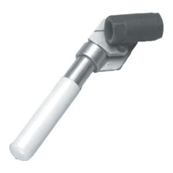
Liquid Drain Ball Valves
Sizes 1/2", 3/4" & 1" (13, 20 & 25mm)
Suitable For Ammonia, Flurocarbons,
Nitrogen and Carbon Dioxide
Features
• Spring Return to Close
• Ball is Relief Ported
• RPTFE Stuffing Box Ring
• All Components of Lever are Stainless
Steel
• Blow-out Proof Stem Design
• Adjustable Packing Gland
Pressure Relief
Determine and provide corrective action against excessive
pressure build up in the valve or piping system due
to thermal expansion. Thermal expansion can create
extreme pressures well above the working pressure
limit of the valve which can cause leaking or bursting of
the valve
Supports
If you choose to connect a flexible hose or other non-ridged
conduit to the valve, the design of such installation must
prevent any "whipping action" that could injure or damage
personnel or equipment. Valve must be immobile.
Fittings
Use only those fittings or piping that are compatible
with the valves being used to prevent breakage and/or
leakage.
Pressure/Temperature Limits
The maximum working pressure limit of the valve is
marked on the valve body. Never exceed the "WOG" rating
which is specified up to 100°F. Temperatures higher than
100°F decrease the maximum working pressure limit.
Refrigerating Specialties Division
310826
BULLETIN 89-00B
March 2007
Installation, Service and Parts Information
Installation
The use of ptfe pipe tape as a sealant is recommended for
threaded valves when making joints. Correct lubrication
of stainless steel pipe threads is especially important
to prevent thread galling. Do not apply excessive torque
when installing the valve. To prevent distortion or damage
to the valve, do not apply torque through the valve. Use
proper supports in handling prefabricated sections and
in final installations. Always test the system before
using.
Maintenance
Do not disassemble the valve while under pressure.
Request a maintenance manual before attempting repairs
to the valve.
1
I S O
9 0 0 1
C E R T I F I E D
Advertisement

Related Manuals for Parker 89-00B


Summary of Contents for Parker 89-00B
- Page 1 Liquid Drain Ball Valves BULLETIN 89-00B Sizes 1/2”, 3/4” & 1” (13, 20 & 25mm) Suitable For Ammonia, Flurocarbons, Nitrogen and Carbon Dioxide Features • Spring Return to Close • Ball is Relief Ported • RPTFE Stuffing Box Ring • All Components of Lever are Stainless...
- Page 2 Liquid Drain Ball Valve Carbon Steel Stainless Steel Shipping Weights Size Part # Part # 1/2" 206548 206551 3/4" 206549 206552 1" 206550 206553 Size inch inch inch inch 1/2" 12.7 1.12 2.25 7.00 3/4" 0.68 3.00 7.00 1" 0.87 1.68 3.37 7.00...
Need help?
Do you have a question about the 89-00B and is the answer not in the manual?
Questions and answers