
Subscribe to Our Youtube Channel
Related Manuals for Parker LINKnet TechBox Series


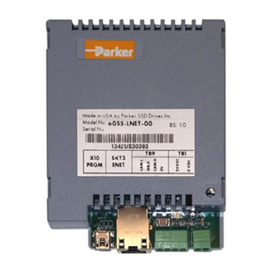
Summary of Contents for Parker LINKnet TechBox Series
- Page 1 WWW.SDS.LTD.UK | 0117 9381800 LINKnet is compatible with the software DSE version 3.00 or greater. Product Manual HA473865U001 Issue 1...
- Page 2 All rights strictly reserved. No part of this document may be stored in a retrieval system, or transmitted in any form or by any means to persons not employed by a Parker SSD Drives company without written permission from Parker SSD Drives.
-
Page 3: Table Of Contents
WWW.SDS.LTD.UK | 0117 9381800 Contents Contents ........................3 Chapter 1 - An Overview .....................5 6053-LNET-00 TechBox ...................5 6055-LNET-00 TechBox ...................5 Further Reading .......................5 Product Features ......................6 Part Number and Identification .................6 Ethernet Protocols supported: ..................6 Software Requirements: ...................6 Hardware supported: ....................6 Chapter 2 - Installation ....................7 Installing the Option ....................7 Wiring Requirements: ....................7... - Page 4 LINKnet Product Manual HA473865U001 Issue 1...
-
Page 5: Chapter 1 - An Overview
WWW.SDS.LTD.UK | 0117 9381800 Chapter 1 - An Overview The LINKnet TechBox/TechCard option allows standard drives to be a part of the LINKnet Ethernet network. A computer may be used to provide supervision and monitoring for each drive and other modules in the system. -
Page 6: Product Features
WWW.SDS.LTD.UK | 0117 9381800 Product Features • Available for AC690+ and DC590+ products • Compact 5H x 3W x 1D inches • Easy snap on installation • Eliminates hard wired signal connections • Standalone processing with built in macros • Auxiliary power supply input for network backup •... -
Page 7: Chapter 2 - Installation
WWW.SDS.LTD.UK | 0117 9381800 Chapter 2 - Installation Installing the Option WARNING Before installing, ensure that the drive power is switched off and cannot be switched on accidentally by other personnel. Wait 5 minutes after disconnecting power before working on any part of the system or removing the covers from the drive. - Page 8 WWW.SDS.LTD.UK | 0117 9381800 6055-LNET-00 6053-LNET-00 TECHBOX TECHBOX External Power Ethernet cable USB to computer USB to computer To Ethernet Switch Figure 4 -Sample LINKnet Network 6053-LNET-00 6055-LNET-00 TECHBOX TECHBOX TB 9 TB 9 TB 9 TB 9 TB 1 TB 1 TB 1 TB 1...
- Page 9 (DSE890) version 3.0 and all subsequent versions support LINKnet. If you have an older version, updates may be obtained simply by contacting Parker SSD Drives Product Support. Firmware cannot be installed into a LINKnet module, over Ethernet. The USB port must be used.
- Page 10 WWW.SDS.LTD.UK | 0117 9381800 CAN peer-to-peer Terminal block – (TB 9) 4 pin connector This option is not implemented yet The CanOpen port will support peer to peer communication of run time data between LINKnet TBs and other LINKnet nodes on a system. The plug-in connectors for TB1 are physically different for the 6055- LNET-00 TechBox, and the 6053-LNET-00 TechBox.
-
Page 11: Fitting The Techbox To The Frame B Ac690+ Drives
WWW.SDS.LTD.UK | 0117 9381800 Fitting the TechBox to the frame B AC690+ Drives WARNING! Ensure that all power is off prior to working on the drive The option is supplied as a “6053- LNET-00 Technology Box” which fits into the front of the AC690+ drive in place of the keypad or blank cover. -
Page 12: Fitting The Techbox To A Dc590+ And Ac690+ Frames C And Above
WWW.SDS.LTD.UK | 0117 9381800 Fitting the TechBox to a DC590+ and AC690+ frames C and above The option is supplied as a “6055-LNET-00 TechBox” which fits into the lower right front of the AC690+C - K drive. Note: The 6055-LNET-00 TechBox does not affect the operation of the 6051/6901 keypad. WARNING! Ensure that all power is off prior to working on the drive. -
Page 13: Chapter 3 - Initial Set-Up
WWW.SDS.LTD.UK | 0117 9381800 Chapter 3 - Initial Set-up There are 2 ways to communicate to the LINKnet Techbox: USB & Ethernet The USB port is primarily intended to use for initial set up of the Techbox and setting up of the IP address. But it can be used to install configurations, install firmware and monitor the entire LINKnet System. -
Page 14: Setting The Node Address
WWW.SDS.LTD.UK | 0117 9381800 module will not appear in the MODULE LIST. Thus if you are setting the IP ADDRESS on multiple Techboxes, after removing the USB cable from the Techbox, DSE must be closed. Then connect the USB cable to the next Techbox, then launch DSE and repeat the procedure. The IP address of the Techbox will be set as long as there is no IP address entered in the System Control block. -
Page 15: Setting The Computer Ip Address For Linknet Access Via Ethernet
WWW.SDS.LTD.UK | 0117 9381800 Setting the computer IP Address for LINKnet access via Ethernet When communicating to the LINKnet via Ethernet, the computer must be on the same subnet. To change the pc settings: 1. From the START menu, open the Control Panel and select “Network and Sharing Center” or “Network Connections”... - Page 16 WWW.SDS.LTD.UK | 0117 9381800 4. Double click on “Internet Protocol Version 4 (TCP/IPv4)” (“Internet Protocol TCP/IP” in XP) and that should bring up the Internet Protocol Dialog that should look something like: 5. Click on the selection “Use the following IP address” and enter 192.168.1.197 for the IP address and 255.255.255.0 for the Subnet mask.
-
Page 17: Configuring The Drive
WWW.SDS.LTD.UK | 0117 9381800 Configuring the Drive The first step in using the technology option is configuring the drive to accept the MMI Menu Map TechBox. The keypad (MMI), DSE890 (SSD Drives’ device level configuration software), must be used to configure the TEC OPTION function block parameters SETUP PARAMETERS inside the drive before commissioning the LINKnet technology option. - Page 18 WWW.SDS.LTD.UK | 0117 9381800 FAULT Range: Enumerated - see below The fault state of the Technology Option card. Enumerated Value : Fault State 0 : NONE: Normal operating mode. 1 : PARAMETER: Confirm that tag exists in the LINK Configuration. 2 : TYPE MISMATCH: Confirm that type of tag is valid.
-
Page 19: Chapter 4 - Using Dse Macros And Templates
WWW.SDS.LTD.UK | 0117 9381800 Chapter 4 - Using DSE Macros and Templates Node Addressing the LINKnet Modules Each LINKnet module must have a unique Node Address assigned to it. The range allowed in DSE is 1 to 127. AC690+ and DC590+ Macros/Templates The DSE program has pre-configured macros for the AC690+ and the DC590+. - Page 20 WWW.SDS.LTD.UK | 0117 9381800 The 590+ macro has some preconfigured inputs and outputs as default. If another tag or parameter is needed, it can be added inside the macro. It is possible to use both the drives’ internal function blocks and the Link function blocks.
- Page 21 WWW.SDS.LTD.UK | 0117 9381800 Modifying inside the macro All the drive functions are available through the TechBox. When using some of the DC590+ drives with firmware version 5.x function blocks, it may be necessary to use the Mini-Link block or a ‘Native drive’ block as the connection point to the TechBox.
- Page 22 WWW.SDS.LTD.UK | 0117 9381800 Note: Internal tags do not get a module address or slot address. The tag appears as a connection point on the outside of the macro. Right mouse clicking on the diamond will allow you to change the name of the tag. This name will appear inside and outside the macro.
- Page 23 WWW.SDS.LTD.UK | 0117 9381800 Using Drive I/O Drive analog and digital inputs are available for use as I/O for the Link system. The DC590+ drive firmware version 5.x requires the use of the MiniLink or system function blocks. The DC590+ drive with firmware v 8.x and the AC690+ drive don’t require the use of the MiniLink or system blocks.
-
Page 24: 690+ Macro Sample Configuration
WWW.SDS.LTD.UK | 0117 9381800 AC690+ Analog and Digital 690+ Macro Sample Configuration Select the 690+ template from the “FILE / NEW” menu. After completing the above steps you should see the 690+ macro without any Link connections as shown below. LINKnet Product Manual HA473865U001 Issue 1... -
Page 25: Watchdog Circuit
WWW.SDS.LTD.UK | 0117 9381800 Watchdog Circuit It is recommended that a Watchdog Circuit be implemented in each LINKnet configuration to stop the drive if there is a loss of Ethernet communications. Presently if there is a loss of Ethernet communications on the LINKnet drive, it will continue to run and not fault. -
Page 26: Chapter 5 - Connecting To The Linknet Techbox
WWW.SDS.LTD.UK | 0117 9381800 Chapter 5 – Connecting to the LINKnet Techbox There are two ways to connect to LINKnet Techbox network. One way is using the USB port and the other way is via Ethernet. The recommended way is the Ethernet, as it is faster. The USB port can be used if there is a problem connecting via Ethernet. -
Page 27: Installing And Updating A Configuration For The First Time
WWW.SDS.LTD.UK | 0117 9381800 Installing and updating a configuration for the first time 1. Using DSE obtain a Module List. This Module List will show all of the modules in the network. 2. Open the LINKnet configuration which you want to install. Make sure the correct motor data is entered in the Motor Data block for the 690+ or in the Configure Drive block for the 590+ drive. -
Page 28: Chapter 6 - Troubleshooting
WWW.SDS.LTD.UK | 0117 9381800 Chapter 6 – Troubleshooting 6053-LNET-00 6055-LNET-00 TECHBOX TECHBOX Health and Run LED’s Health and Run are drive functions and are not associated with the operation of the technology feature. On the AC690+ frame B the Techbox is mounted in place of the keypad or blank cover. The Run and Health LED’s from the keypad are replicated on the face of the techbox. - Page 29 WWW.SDS.LTD.UK | 0117 9381800 Module LED Status – NCP State Techbox State LED Indication Blink Code (1second 1 second period Initializing Initializing Green 10 % : Off 90 % 1 Halt Config Red 95% : Green 5% No Config Fault Red 50% : Off 50% L-Error Fault...
-
Page 30: Chapter 7 - Programming Ts8000
WWW.SDS.LTD.UK | 0117 9381800 Chapter 7 – Programming TS8000 Modbus Settings There are some settings/limits that are needed for the TS8000 communications. The Maximum Segment (Ethernet packet) size is 232: In the Extended Settings, the Register Writes and the Frame Register Limits need to be set as shown below: LINKnet Product Manual HA473865U001 Issue 1... -
Page 31: Appendix A - Sequencing States
WWW.SDS.LTD.UK | 0117 9381800 Appendix A - Sequencing States On Power Up the sequence is as follows: 1. When the drive is powered up, data is transferred from the Drives E Squared PROM to the Drives RAM. 2. Then data is transferred from the Techbox’s Flash to the Techbox’s RAM. 3. - Page 32 FI – Finland, Vantaa Tel: +351 22 999 7360 Tel: +358 (0)20 753 2500 parker.portugal@parker.com parker.finland@parker.com Parker Hannifin Corporation © 2014 Parker Hannifin Corporation HA473865U001 SSD Drives Division LINKnet TechBox 9225 Forsyth Park Dr. Product Manual Charlotte, NC 28273 USA Tel: (704) 588-3246 Fax: (704) 588-4806 info.us.ssd@parker.com...
Need help?
Do you have a question about the LINKnet TechBox Series and is the answer not in the manual?
Questions and answers