Table of Contents
Advertisement
Quick Links
FLUID CONTROL DIVISION
Parker Hannifin Corporation
95 Edgewood Avenue
New Britain, CT 06051
Telephone (860) 827-2300
INSTALLATION, OPERATING & MAINTENANCE INSTRUCTIONS
WARNING
GENERAL
SAFETY
INSTALLATION
FAILURE OR IMPROPER SELECTION OR IMPROPER
USE OF THE PRODUCTS AND/OR SYSTEMS
DESCRIBED HEREIN OR RELATED ITEMS CAN
CAUSE DEATH, PERSONAL INJURY AND PROPERTY
DAMAGE.
This document and other information from Parker Hannifin
Corporation, its subsidiaries and authorized distributors
provide product and/or system options for further
investigation by users having technical expertise. It is
important that you analyze all aspects of your application,
including consequences of any failure, and review the
information concerning the product or system in the
current product catalog. Due to the variety of operating
conditions and applications for these products or systems,
the user, through its own analysis and testing, is solely
responsible for making the final selection of the products
and systems and assuring that all performance, safety
and warning requirements of the application are met.
The products described herein, including without
limitation, product features, specifications, designs,
availability and pricing, are subject to change by Parker
Hannifin Corporation and its subsidiaries at any time
without notice.
Carefully read installation, operation and maintenance
procedures prior to installing or servicing valve.
Do not use valve as a safety shut-off valve when making
repairs.
Do not install a valve before depressurizing system down
to atmospheric pressure.
Care must be taken to ensure that the valve materials
selected are suitable for the media being handled. Parker
assumes no liability for damage caused by improper
material selection in the case of corrosion from aggressive
media.
Caution: Do not, at any time, make any alteration or
modifications to any angle body valves without the
express and written approval of Parker's Fluid Control
Division.
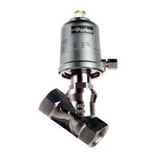
SERIES 810 ANGLE BODY VALVES
2-WAY NORMALLY CLOSED
2-WAY NORMALLY OPEN
!
INSTRUCTIONS
BEFORE
IOM SERIES 810
DESCRIPTION
These valves are 2-way valves. The product line contains
both normally closed (N.C.) and normally open (N.O.)
valves in a bronze and stainless construction. The valves
can be actuated pneumatically or hydraulically. The pilot
operated models require a minimum operating pressure
differential to ensure valve operation.
Pilot valves may be ordered with either NEMA 2, 4, 4X
integrated coils for ordinary locations or NEMA 4, 4X, 7,
and 9 for hazardous locations: Divisions I and II; Class I,
Groups A, B, C, and D; Class II, Groups E, F, and G.
PRINCIPLES OF OPERATION
2-way SERIES 810 - NORMALLY CLOSED VALVES
The angle seat valve is kept closed by a spring which
presses against a piston and piston rod forcing the
seating seal tightly against the valve seat. When pressure
is applied to the actuator pilot connection, the piston,
piston rod and thus the seating seal are raised opening
the valve.
The valve tightly closes when pressure is removed from
the pilot connection.
The maximum permitted angle body valve pressure and
pilot valve pressure and temperature ranges are
described on the valve nameplate.
2-way SERIES 810- NORMALLY OPEN VALVES
The angle seat valve is kept open by a spring which
presses upward on a piston and piston rod forcing the
seating seal off the valve seat. When pressure is applied
to the actuator pilot connection, the piston, piston rod and
thus the seating seal are driven down tightly closing the
valve.
The valve opens when pressure is removed from the pilot
connection.
The maximum permitted angle body valve pressure and
pilot valve pressure and temperature ranges are
described on the valve nameplate.
CAUTION:
A minimum pilot operating pressure
differential
is required for proper angle valve
operation.
Page 1
Advertisement
Table of Contents

Subscribe to Our Youtube Channel
Related Manuals for Parker 810 Series


Summary of Contents for Parker 810 Series
- Page 1 Parker Hannifin Corporation and its subsidiaries at any time 2-way SERIES 810- NORMALLY OPEN VALVES without notice.
- Page 2 Flanges: For flanged mounted valves, follow applicable Installation Instructions ANSI, DIN, JIS specifications for bolting and torque recommendations. The bolt should pass first through the Mounting position and pressure limits: Valves can be mounting flange before engaging the valve flange. Allow mounted directly on piping and are designed to operate in proper spacing for installing the valve.
- Page 3 Note: Depending on service conditions, fluid being used, COIL ASSEMBLY filtration, and lubrication, it may be required to periodically clean and/or replace worn components. ASSEMBLY INSTRUCTIONS FOR ALL COIL TYPES CAUTION: Do not expose plastic or elastomeric materials Position coil (as described below) on the sleeve, install to any type of commercial cleaning fluid.
- Page 4 Diagram of Normally Closed Valve Diagram of Normally Open Valve WARNING: The actuator is spring loaded. WARNING: The actuator is spring loaded. Dismantle actuator with tools provided in repair kit. Dismantle actuator with tools provided in repair kit. Page 4...
- Page 5 TROUBLE SHOOTING PROBLEM PROCEDURE Angle Body Valve fails to operate. 1. Check that pilot air supply is properly connected. 2. Verify that pilot air supply meets the minimum pressure required to actuate the specific angle valve model number. 3. Check pilot control valve functionality. Make sure that pressure complies with pilot control valve nameplate rating and pressure is supplied to actuator head through the output port of the pilot valve.
- Page 6 Any unauthorized work performed on the product by the purchaser or by third parties can impair its function and relieves Parker Hannifin of all warranty claims and liability for any misuse and resulting damage.
Need help?
Do you have a question about the 810 Series and is the answer not in the manual?
Questions and answers