Advertisement
Quick Links
Bulletin HY11-3236-M1/UK
Installation Manual
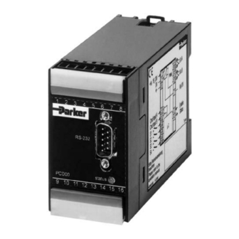
Series PCD 00A-400
Design ³ 19
Electronic for
Proportional Pressure/
Throttle Valves
Parker Hannifin
Manufacturing Germany GmbH & Co. KG
Hydraulic Controls Division Europe
Gutenbergstr. 38
41564 Kaarst, Germany
Tel.: (+49) 181 99 44 43 0
E-mail: valveshcd@parker.com
Copyright © 2016, Parker Hannifin Corp.
Advertisement

Related Manuals for Parker Series PCD 00A-400


Summary of Contents for Parker Series PCD 00A-400
- Page 1 Design ³ 19 Electronic for Proportional Pressure/ Throttle Valves Parker Hannifin Manufacturing Germany GmbH & Co. KG Hydraulic Controls Division Europe Gutenbergstr. 38 41564 Kaarst, Germany Tel.: (+49) 181 99 44 43 0 E-mail: valveshcd@parker.com Copyright © 2016, Parker Hannifin Corp.
-
Page 2: Offer Of Sale
The user must analyze all aspects of the application, follow applicable industry standards, and follow the information concerning the product in the current product catalog and in any other materials provided from Parker or its subsidiaries or authorized distributors. - Page 3 Electronic Prop. Pressure/Throttle Valves Installation Manual Series PCD 00A-400 Parker electronic modules series PCD00A-400 for rail mounting are compact, easy to install and provide time-saving wiring by disconnectable ter- minals. The digital design of the circuit results in good accuracy and optimal adaption for propor- tional pressure/flow control valves by a comfortable interface program.
- Page 4 Electronic Prop. Pressure/Throttle Valves Installation Manual Series PCD 00A-400 Technical Data General Model Module package for snap-on mounting on EN 50022 rail Package material Polycarbonate Inflammability class V0 acc. UL 94 Installation position Ambient temperature range [°C] -20...+60 Protection class NEMA 1/IP20 acc.
- Page 5 Electronic Prop. Pressure/Throttle Valves Installation Manual Series PCD 00A-400 Signal Flow Diagram A Commands Additionally to the external analogue command S2 (Pin 14) and S3 (Pin 15) has a higher priority inputs (Pins 5-7 and 6-7), the PCD00A-400-elec- than S4 (Pin 16).
-
Page 6: Unit Function
Electronic Prop. Pressure/Throttle Valves Installation Manual Series PCD 00A-400 Ramp-function / Min-Max-function The PCD00A-400-electronic includes two internal ally a current step may be programmed (Min) and programmable ramps for each channel. Addition- / or the current may be limited (Max) for each... - Page 7 Electronic Prop. Pressure/Throttle Valves Installation Manual Series PCD 00A-400 Connection Examples Certainly combinations and / or modifications of these examples are possible. The priority of the digital inputs over the analogue inputs has to be kept in mind! Via parameter N=1 all four digital inputs may be dedicated to channel A.
- Page 8 Electronic Prop. Pressure/Throttle Valves Installation Manual Series PCD 00A-400 Pinning Description Description + supply 18...30 VDC channel A GND supply 0 VDC channel A Enable input 9...30 VDC channel B Status output 0 VDC / 18...30 VDC channel B Cmd. A-channel 0...+10 VDC...
- Page 9 Electronic Prop. Pressure/Throttle Valves Installation Manual Series PCD 00A-400 Installation guide to electronic modules to provi- The module has to be mounted within a conductive, sion of electromagnetic compatibility shielded enclosure. Usable is i.e. an EMC-approved control cabinet. A perfect grounding of the enclosure Power Supply is mandatory (see also chapter “Grounding“).
Need help?
Do you have a question about the Series PCD 00A-400 and is the answer not in the manual?
Questions and answers