
Subscribe to Our Youtube Channel
Related Manuals for Parker Sporlan B5D Series


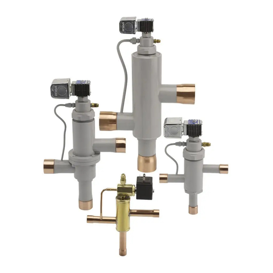
Summary of Contents for Parker Sporlan B5D Series
- Page 1 May 2016 / Bulletin 30-21 Bulletin 30-21 – Page 1 3-Way Valves Installation and Servicing Instructions...
-
Page 2: Table Of Contents
The user must analyze all aspects of the application, follow applicable industry standards, and follow the information concerning the product in the current product catalog and in any other materials provided from Parker or its subsidiaries or authorized distributors. -
Page 3: 3-Way Heat Reclaim Valves
Bulletin 30-21 – Page 3 3-Way Heat Reclaim Valves upper pilot port is closed to suction. High side pressure build up on top of the piston moves the piston-seat assembly to B5D, 8D, 12D, 16D, 8D-HP, 12D-HP, close the normal con dens er port and open the reclaim (upper) main port. -
Page 4: Head Pressure Control For Reclaim Systems
Page 4 – Bulletin 30-21 HEAD PRESSURE CONTROL FOR Figure 3 shows piping schematics only to illustrate the general in stal la tion of the Heat Reclaim Valves. Sporlan recommends RECLAIM SYSTEMS that rec og nized piping references be consulted for assistance When employing heat reclaim on a refrigeration system, the addi- in piping pro ce dures. -
Page 5: Typical Wiring Schematics And Electrical Considerations
Bulletin 30-21 – Page 5 TYPICAL WIRING SCHEMATICS & ELECTRICAL CONSIDERATIONS Single Compressor Systems Wiring of single compressor units may require the use of It is always a good idea to check with the equipment man- relays to prevent high to low side bleed during periods ufacturer for recommendations on the application of heat when the compressor is not circulating refrigerant. -
Page 6: 3-Way Split Condenser Valves
Page 6 – Bulletin 30-21 3-Way Split Condenser Valves assembly to suction pressure 2. The cavity below the piston is exposed to high pressure. The resulting pressure differential 8D-SC, 12D-SC, 16D-SC, S8D-SC, S12D-SC, S16D-SC across the piston moves the piston-seat assembly up to close the upper (Condenser B) port. -
Page 7: Installation
Bulletin 30-21 – Page 7 3-Way Hot Gas Defrost Valves INSTALLATION Piping Suggestions 10G79B, 10G711B, 10G711C Valves must be installed in a horizontal or vertical position with the coil level with, or above the valve body. Install Split INSTALLATION Condenser Valves so the connections are in the proper flow direction as shown in Figure 7. -
Page 8: Service
Page 8 – Bulletin 30-21 SERVICE 10G79B and Service parts for these valves may be ordered through your 10G711B local Sporlan whole sal er. If a pilot assembly kit is required, note that they – unlike the internal parts kits – are not in ter change able. For a list of replacement part kits, see table on page 13. -
Page 9: 180 Solenoid Pilot Control
Bulletin 30-21 – Page 9 Type 180 Solenoid superheat at the outlet of the evaporator. However, when an abnormal pressure is introduced which upsets the equilibri- Pilot Control Valve um, another effect may be accomplished. The principle upon which the 180 Solenoid Pilot Control influences the expansion valve action is by the creation of a pressure under the valve FEATURES diaphragm, which is higher than the bulb pressure. -
Page 10: Application
Page 10 – Bulletin 30-21 Upon re-energizing the solenoid coil, the low pressure port Standard Maximum Refrigerant of the 180 opens and allows instantaneous relief of pressure Operating Pressure under the thermostatic expansion valve diaphragm and nor- 12, 134a 50 psig (3.5 bar) mal operation of the thermostatic expansion valve. -
Page 11: Installation
Bulletin 30-21 – Page 11 SPECIFICATIONS On double-ported thermostatic expansion valves, such as Sporlan’s Types V and W, the chance of dirt causing leakage MKC-2 Coil is increased since either port could be partially blocked open. If this occurs, the leakage would be even greater since both Type 180 Standard Coil Ratings ports would leak because the seating discs operate on the... -
Page 12: General Information
Page 12 – Bulletin 30-21 4. In the event that full liquid line pressure is available 5D valve, the pilot valve body MUST be supported when tight- and the bottom port is NOT leaking, then it is necessary ening the 1/4” flare connection. Failure to do either of the above may cause leaks or valve damage. -
Page 13: Replacement Parts Kits
Bulletin 30-21 – Page 13 Manufactured with Split Cast Iron 3-Way Valve Piston Rings and Honed Body Bore 8D7B 7-96 & Earlier 8D9B 7-96 & Earlier 12D11B 1-94 & Earlier Design “AA” 12D13B 1-94 & Earlier Tetraseal (Groove) 16D17B 4-91 & Earlier The parts kit contains two different gaskets for the pilot valve. -
Page 14: Recommended Torque
Page 14 – Bulletin 30-21 RECOMMENDED TORQUE Enclosing Tube Pilot Valve Lower Body Body Flange Valve Series Coil Screw Locknut Assembly Locknut Locknut Cap Screw S8D, S8D-HP, 8D, 8D-SC, — 10-15 60-65 8D-HP, S8D-SC S12D, S12D-HP, — 15-18 10-15 60-65 12D, 12D-SC, S12D-SC —... -
Page 15: Terms Of Sale With Warranty Limitations
OFFER OF SALE The goods, services or work (referred to as the “Products”) offered by Parker-Hannifin Corporation, its subsidiaries, groups, divisions, and authorized distributors (“Seller”) are offered for sale at prices indicated in the offer, or as may be established by Seller. The offer to sell the Products and acceptance of Seller’s offer by any customer (“Buyer”) is contingent upon, and will be governed by all of the terms and conditions contained in this Offer of Sale. - Page 16 © 2016 Parker Hannifin Corporation. Bulletin 30-21 / 52016 Parker Hannifin Corporation Sporlan Division 206 Lange Drive • Washington, MO 63090 USA phone 636 239 1111 636 239 9130 www.sporlan.com...
Need help?
Do you have a question about the Sporlan B5D Series and is the answer not in the manual?
Questions and answers