Advertisement
Quick Links
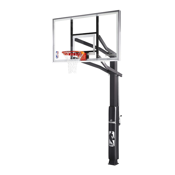
In-Ground Basketball System Owners Manual
WARNING!
PLEASE ENSURE
that (4) steel spacers
are in place between
Board Frame and Rim
Prior to tightening bolts.
(SEE PAGE 16)
FAILURE TO FOLLOW OPERATING
INSTRUCTIONS COULD RESULT IN
INJURY OR DAMAGE TO PROPERTY.
Write Model Number
From Box Here:
Toll-Free Customer Service Number for U.S: 1-800-558-5234 Australia: 1300 367 582
Spalding Internet Address: http://www.spalding.com
© COPYRIGHT 2018 by Russell Brands, LLC
Système de basket-ball dans le sol
Propriétaires Manuel garantie
Para la última información de garantía del sistema de baloncesto
Por favor visite el sitio web de Spalding Basketball en www.Splading.com
Póngase en contacto con servicio al cliente de Spalding en teléfono # 1-800-558-5234
www.spalding.com.au
1
WARNING!
READ AND UNDERSTAND
OPERATOR'S MANUAL
BEFORE USING THIS UNIT.
FAILURE TO FOLLOW
OPERATING INSTRUCTIONS
COULD RESULT IN INJURY
OR DAMAGE TO PROPERTY.
10/18
ID# M866047
Advertisement

Related Manuals for SPALDING In-Ground Basketball System


Summary of Contents for SPALDING In-Ground Basketball System
- Page 1 Para la última información de garantía del sistema de baloncesto BEFORE USING THIS UNIT. Por favor visite el sitio web de Spalding Basketball en www.Splading.com Póngase en contacto con servicio al cliente de Spalding en teléfono # 1-800-558-5234 FAILURE TO FOLLOW OPERATING INSTRUCTIONS COULD RESULT IN INJURY OR DAMAGE TO PROPERTY.
-
Page 2: Safety Instructions
IMPORTANT! WRITE MODEL NUMBER FROM BOX ONTO PAGE 1 OF THIS OWNERS MANUAL SAFETY INSTRUCTIONS WARNING FAILURE TO FOLLOW THESE SAFETY INSTRUCTIONS MAY RESULT IN Read and understand warnings SERIOUS INJURY, PROPERTY DAMAGE AND WILL VOID WARRANTY. listed below before using this product. Owner must ensure that all players know and follow these rules for safe Failure to follow these warnings operation of the system. - Page 3 Garantía de dueños Para la última información de garantía del sistema de baloncesto Por favor visite el sitio web de Spalding Basketball en www.Spalding.com 1-800-558-5234 Póngase en contacto con servicio al cliente de Spalding en teléfono # 08/08 ID# M86604C1 05/2013...
-
Page 4: Parts List
Spacer, 0.50” I.D. x 0.75” x 4” Long 701299 Rod, Threaded Assembly, 5/8-11 x 19.8”, Zinc 202666 Name Plate, Hydra-Rib 3" High 204521 Name Plate, Spalding 4" Wide Cover, Rim 978850 Yoke, Upper, Center, Pole 988855 Yoke, Lower, Center, Pole 204984 Bolt, Hex, 5/8-11 x 2.5”... - Page 5 HARDWARE IDENTIFIER (BOLTS AND SCREWS) Item #23 (1)* Item #20 (1) Item #7 (4) Item #29 (4) Item #34 (4) Item #28 (3) Item #19 (4)
- Page 6 HARDWARE IDENTIFIER (NUTS, WASHERS AND SPACERS) Item #6 (4) Item #26 (1) Item #27 (4)* Item #21 (16) Item #24 (9) Item #5 (4) Item #22 (9)* Item #25 (8) Item #33 (2)* Item #13 (1) Item #38 (1) or this one HARDWARE IDENTIFIER (OTHER) Item #37 (1) Item #35 (1) 208482...
- Page 7 Ensure ground is level with playing surface, then dig pole hole. 24" (61 cm) WARNING! 48" (121.9 cm) 24" (61 cm) 24" (61 cm) 2 6" (15,2 cm) GROUND SURFACE PLAYING SURFACE 48" (121.9 cm) CONTACT UTILITIES BEFORE DIGGING. XG02.EPS NOTE: Check building codes for your location to determine apropriate hole depth for cement.
-
Page 8: Side View
Fill hole with concrete. Tamp down concrete to release air pockets and build drainage hill. DRAINAGE HILL 1" (2.54 cm) PLAYING SURFACE SIDE VIEW HR83005.EPS Insert rebar (10) through holes in ground tube assembly (2) as shown. 211560... - Page 9 Insert ground tube assembly (2) into cement as shown. Move assembly around to release any air pockets in cement, then rest mounting plate on cement drainage hill. Apply some pressure to level mounting plate on top of drainage hill. Level mounting plate and square with playing surface. Clean off any excess cement on mounting plate at this time and place washers (24) on mounting bolts (19).
- Page 10 Rest top of pole (1) on a piece of scrap wood (not included) and line up holes in pole to holes in mounting plate (2) as shown. WARNING! PLAYING SURFACE PLAYING SURFACE SCRAP WOOD (NOT INCLUDED) THREE CAPABLE ADULTS REQUIRED FOR THIS PROCEDURE.
- Page 11 WARNING! TWO people are required to lift pole into position so that the threaded assembly rod (14) can be installed and secured by the THIRD person. THREE CAPABLE ADULTS While pole is being supported by TWO REQUIRED FOR THIS capable adults, position rod (14) and lock PROCEDURE.
- Page 12 While still in forward position, attach both upper and lower yokes (17 and 18) to pole as shown. Pole is being supported by TWO capable adults during assembly. WARNING! THREE CAPABLE ADULTS REQUIRED FOR THIS PROCEDURE. FAILURE TO FOLLOW THIS WARNING COULD RESULT IN SERIOUS INJURY AND/ OR PROPERTY DAMAGE.
- Page 13 Attach elevator adjustment (12) to lower yoke (18). Pole is being supported by TWO capable adults during assembly. WARNING! THREE CAPABLE ADULTS REQUIRED FOR THIS PROCEDURE. FAILURE TO FOLLOW THIS WARNING COULD RESULT IN SERIOUS INJURY AND/ OR PROPERTY DAMAGE.
- Page 14 Attach elevator adjustment (12) to pole bracket. Pole is being supported by TWO capable adults during assembly. WARNING! THREE CAPABLE ADULTS REQUIRED FOR THIS PROCEDURE. FAILURE TO FOLLOW THIS WARNING COULD RESULT IN SERIOUS INJURY AND/ OR PROPERTY DAMAGE.
- Page 15 Attach backboard (8) to upper and lower yokes (18 and 17). While pole is being supported by TWO capable While pole is being supported by TWO adults. Next, hinge board to match up with holes capable adults. First attach board (8) to in lower yoke (18), FIG.
- Page 16 IMPORTANT!: FOLLOW THESE INSTRUCTIONS IF YOUR SYSTEM HAS A GLASS BACKBOARD - ONLY! WARNING! PLEASE ENSURE THAT FOAM PAD IS PLACED ON TOP OF ALL 4 STEEL SPACERS AND HAS ADHERED TO GLASS OF THE BACKBOARD BEFORE ATTACHING YOKES. FAILURE TO FOLLOW THESE INSTRUCTIONS COULD RESULT IN PERSONAL INJURY OR DAMAGE TO PROPERTY. STEP 1.
- Page 17 WARNING! PLEASE ENSURE THAT FOAM PAD IS PLACED ON TOP OF ALL 4 STEEL SPACERS AND HAS ADHERED TO GLASS OF THE BACKBOARD BEFORE ATTACHING YOKES. FAILURE TO FOLLOW THESE INSTRUCTIONS COULD RESULT IN PERSONAL INJURY OR DAMAGE TO PROPERTY. WARNING! Before starting rim assembly, tighten nut (26) until it is positioned 6-3/4”...
-
Page 18: Outside View
Set-up For Left Side Set-up For Right Side Apply height indicator labels (32 & 31) to height indicators (30). 7 8 9 10 7 8 9 10 Attach height indicators to left side of lower yoke in area shown by turning screws (29) into place with a phillips-head screwdriver. IMPORTANT! NOTE ORIENTATION OF HEIGHT... - Page 19 Upright pole (1) by tightening nut (26). Using 15/16” wrench, turn nut (26) clockwise to begin standing pole upright. Continue to turn nut (26) until pole has come to rest against washers (24) and pole is vertical. Once pole is in its final position, install washers (24) and nuts (25) onto J-bolts (19) and fully tighten to secure pole to anchor plate (2).
- Page 20 After pole has been secured to the anchor plate (2) loosen nut (26), remove cotter pin (37), and pull out pin (36). This will allow the removal of the threaded assembly rod (14) which is no longer necessary for the remainder of the assembly and installation of system. WARNING! ONLY AFTER THE ANCHOR PLATE HAS BEEN...
- Page 21 Check system leveling. Pole (1) should be Apply height adjustment label (11). level in all directions. After system is leveled, completely tighten all nuts (25). Adjust system by turning crank until desired height is reached per height indicator (30). CHECK LEVEL CHECK LEVEL...
Need help?
Do you have a question about the In-Ground Basketball System and is the answer not in the manual?
Questions and answers