Table of Contents
Advertisement
Quick Links
UNIVERSAL ELEVATOR MOUNT
Toll-Free Customer Service Number
U.S.:
1-800-558-5234
Canada:
1-800-284-8339
Europe:
+353 51 379777
Australia: 1300 367 582
www.spalding.com
WARNING
READ AND UNDERSTAND THE OPERATOR'S
MANUAL BEFORE USING THIS UNIT.
FAILURE TO FOLLOW THE OPERATING
INSTRUCTIONS COULD RESULT IN INJURY
OR DAMAGE TO PROPERTY.
Owner's Manual
Model Number:
(found on product box)
05/21 ID# M3160013
Advertisement
Table of Contents

Subscribe to Our Youtube Channel
Related Manuals for SPALDING U-Turn Lift System


Summary of Contents for SPALDING U-Turn Lift System
- Page 1 U.S.: 1-800-558-5234 Canada: 1-800-284-8339 Europe: +353 51 379777 Australia: 1300 367 582 www.spalding.com WARNING READ AND UNDERSTAND THE OPERATOR’S MANUAL BEFORE USING THIS UNIT. FAILURE TO FOLLOW THE OPERATING INSTRUCTIONS COULD RESULT IN INJURY OR DAMAGE TO PROPERTY. 05/21 ID# M3160013...
-
Page 2: Table Of Contents
FAILURE TO FOLLOW OPERATING INSTRUCTIONS COULD RESULT IN INJURY OR PROPERTY DAMAGE. Contact Questions or missing parts? Do NOT go back to the store! Email: warrantyservice@custserv.fotlinc.com Customer Service 1-800-558-5234 Toll-Free Number: Mailing Address: Spalding PO Box 90015 Bowling Green, KY 42102... -
Page 3: Warranty
Warranty Warranty For the very latest Basketball System Warranty information, please visit www.Spalding.com or call Spalding Customer Service at 1-800-558-5234. Safety Information WARNING FAILURE TO FOLLOW THESE SAFETY INSTRUCTIONS MAY RESULT IN SERIOUS INJURY OR PROPERTY DAMAGE AND WILL VOID THE WARRANTY. -
Page 4: Test-Fit Close Tolerance Bolts
Test-Fit Close Tolerance Bolts Test-Fit Close Tolerance Bolts To ensure optimal playability of the backboard system, a close tolerance fit between the elevator components and hardware is required. Test-fit large bolts into large holes of elevator tubes, backboard brackets, and triangle plates. Carefully rock them in a circular motion to remove any excess paint from holes, if necessary. - Page 5 Package Contents NUTS AND WASHERS 203099Hex Locknut (Nylon Insert) 5/16-18 202651 0.53” ID x 1” OD Locknut, Hex Head, 1/2-13 (x9) Washer, Flat, 5/16 (x12) 10 Washer, Flat, 1/2 (x10) 11 Locknut, Nylon Insert, 5/16 (x6) 13 Nut, Hex, Locking 1/4-20 (x1) 32 Washer, Flat, Nylon (x4) 33 Locknut, Nylon Insert, 3/8-16 (x4) 34 Washer, 3/8 (x4)
- Page 6 Package Contents MOUNTING BRACKET HARDWARE HEIGHT ADJUSTMENT Size = 4" x 3. Corner Radiu TO ADJUST BACKBOARD: Die Cut Labe Position looped end of crank onto hook as shown. 3.25 Mil Viny Rotate crank handle to All Temp. Per raise or lower backboard 1 Mil.
-
Page 7: Tools & Materials For Assembly
Tools & Materials for Assembly Tools & Materials for Assembly NOTE Due to various mounting methods, additional tools and materials may be required. 2 Capable Adults Tape Measure Step Ladder (8 ft.) Level Pencil (OPTIONAL) Socket Wrench Wrench Drill and Drill Bit (3/8") Needle-Nose Pliers Extension 7/16", 1/2", 9/16", 3/4"... -
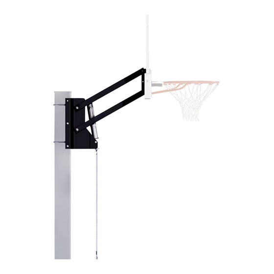
Page 8: Assemble The Elevator Mount
MAY HAVE OCCURRED DURING SHIPMENT. CRACKS IN THE BACKBOARD COULD RESULT IN SUDDEN BREAKAGE. IF BACKBOARD IS DAMAGED IN ANY WAY PRIOR TO OR AFTER ASSEMBLY, CALL TOLL-FREE NUMBER: U.S.: 1-800-558-5234; CANADA: 1-800-284-8339; WWW.SPALDING.COM. NOTE Sections A-D are options for elevator mounting. - Page 9 Assemble the Elevator Mount B - Completed Elevator Mount to a Round Pole: C - Completed Elevator Mount to a Wall or Flat Surface: D - Completed Extension Arm Mounting:...
- Page 10 Assemble the Elevator Mount ASSEMBLE THE ELEVATOR MOUNT TO A SQUARE POLE 1. At a position near the ground surface, assemble pole bracket (17) to square pole using u-bolts (29), washers (10) and nuts (8). 2. Attach jack support brackets (18 & 19) to pole bracket (17) using bolts (3), washers (9) and nuts (11).
- Page 11 Assemble the Elevator Mount ASSEMBLE THE ELEVATOR MOUNT TO A ROUND POLE 1. At a position near the ground surface, assemble pole bracket (17) to round pole using u-bolts (1), clamps (2), washers (34) and nuts (33) as shown. 2. Attach jack support brackets (18 & 19) to pole bracket (17) using bolts (3), washers (9) and nuts (11) as shown.
- Page 12 Assemble the Elevator Mount ASSEMBLE THE ELEVATOR MOUNT TO A WALL OR FLAT SURFACE 1. Secure pole bracket (17) to flat solid surface. Install bolt heads outside for safety reasons. Not Included 2. Attach jack support brackets (18 & 19) to pole bracket (17) using bolts (3), washers (9) and nuts (11) as shown.
- Page 13 Assemble the Elevator Mount NOTE Hardware for these procedures are not included due to various roof and wall construction materials and design structure. INSTALL THE ELEVATOR MOUNT TO A FLAT OR ANGLED ROOF 1. Attach struts (23), angle brackets (26 & 27), and jack support brackets (18 & 19) to pole bracket (17) with bolts (3), washers (9) and nuts (11) as shown.
- Page 14 Assemble the Elevator Mount INSTALL THE ELEVATOR MOUNT TO A FLAT OR ANGLED ROOF 3. Note position of angle brackets (26 & 27) in relation to pole bracket per style roof. #26 & #27 #26 & #27 4. Keep assembly upright and position struts (23) on desired location on roof approx.
-
Page 15: Assemble The Elevator Structure/Mechanism
Assemble the Elevator Structure/Mechanism Assemble the Elevator Structure/Mechanism Required Parts: #6 Bolt, Hex Head, 1/2-13 x 7” #7 Label, Warning #8 Locknut, Hex Head, 1/2-13 #10 Washer, Flat, 1/2 Long #14 Spacer, 1 .8 Long #21 Sleeve, Plastic, Height- #24 Screw Jack Assembly #28 Label, Height-Indicator Indicator #30 Tube, Elevator... - Page 16 Assemble the Elevator Structure/Mechanism ASSEMBLE THE ELEVATOR 1. Identify the elevator tubes (30). Toward Mount Toward board 2. Attach elevator tubes (30) to the jack support brackets (18 & 19) using bolts (6), washers (10), spacers (31 & 32) and nuts (8) as shown.
- Page 17 ergr g Assemble the Elevator Structure/Mechanism ASSEMBLE THE ELEVATOR 3. Attach height decal (28) on screw jack (24). Align lower edge of decal (28) with screw jack bottom. 4. Place cover (21) over screw jack (24). 5. Insert spacer (16) into screw jack assembly (24) as shown.
- Page 18 Assemble the Elevator Structure/Mechanism ATTACH THE WARNING LABEL 1. Adhere the warning label (20) in a clearly REGULATION RIM HEIGHT visible place. IS 10 FEET (3 .05 m) . MUNSELL NOTATION Value Chroma 5.0 YR 6.0/15 Equiv. CIE Data (Y%) 30.05 0.5510 0.4214...
-
Page 19: Backboard Mounting
Backboard Mounting Backboard Mounting Required Parts: #4 Spacer, 1 .8 Long #5 Bolt, Hex Head, 1/4-20 x 2-1/4” Long #6 Bolt, Hex Head, 1/2-13 x 7” Long #8 Locknut, Hex Head, 1/2-13 #13 Nut, Hex, Locking 1/4-20 #15 Spacer, Plastic, 1” Long #16 Spacer, Metal, .75 O .D ., 4”... - Page 20 Backboard Mounting ATTACH A COMPOSITE STYLE BACKBOARD 1. Assemble backboard brackets (20) using bolt (5) spacer (4) and nut (13) as shown. 2. Attach backboard using hardware shown. 3. Bend support brackets (20) to line up with upper holes in backboard.
-
Page 21: Operation
Operation ATTACH A STEEL-FRAMED STYLE BACKBOARD 1. Attach backboard using hardware shown. Operation HEIGHT ADJUSTMENT ADJUSTING THE HEIGHT WARNING TO ADJUST BACKBOARD: DO NOT ALLOW CHILDREN TO ADJUST THE HEIGHT. Position looped end of 1. Position the looped end of the crank (22) onto the hook. -
Page 22: Parts List
Parts List Parts List Item Part No . Description Item Part No . Description 205807 U-Bolt, Round 3/8-16 x 4.68 908529 Bracket, Jack Support, Left 202675 Clamp, Saddle 910846 Bracket, Elevator Bolt, Hex Head, 5/16-18 x 1-1/4” 203589 206234 Sleeve, Plastic, Height Indicator Long 201129 Spacer, 1.8 Long... - Page 24 APPELEZ LE NUMÉRO SANS FRAIS : 1.800.558.5234 | www.hu ysports.com Failure to follow these warnings may result in www.spalding.com serious injury and/or property damage. English only - board warning Owner must ensure that all players know and follow these rules...
Need help?
Do you have a question about the U-Turn Lift System and is the answer not in the manual?
Questions and answers