Table of Contents
Advertisement
Available languages
Available languages
Quick Links
PORTABLE BASKETBALL SYSTEM
Toll-Free Customer Service Number
U.S.:
1-800-558-5234
Canada:
1-800-284-8339
Europe:
+353 51 379777
Australia: 1300 367 582
www.spalding.com
WARNING
READ AND UNDERSTAND THE OWNER'S
MANUAL BEFORE USING THIS UNIT.
FAILURE TO FOLLOW THE OPERATING
INSTRUCTIONS COULD RESULT IN INJURY
OR DAMAGE TO PROPERTY.
Owner's Manual
Model Number:
ITM. / ART. 2622007
(found on product box)
04/22 ID# M6A93304
ENGLISH
Advertisement
Chapters
Table of Contents

Related Manuals for SPALDING 2622007


Summary of Contents for SPALDING 2622007
- Page 1 Model Number: ITM. / ART. 2622007 (found on product box) ENGLISH PORTABLE BASKETBALL SYSTEM Owner’s Manual Toll-Free Customer Service Number U.S.: 1-800-558-5234 Canada: 1-800-284-8339 Europe: +353 51 379777 Australia: 1300 367 582 www.spalding.com WARNING READ AND UNDERSTAND THE OWNER'S MANUAL BEFORE USING THIS UNIT.
-
Page 2: Table Of Contents
Contact Questions or missing parts? Do NOT go back to the store! Email: warrantyservice@custserv.fotlinc.com U.S.: 1-800-558-5234 Canada: 1-800-284-8339 Customer Service Toll-Free Number: Europe: +353 51 379777 Australia: 1300 367 582 Mailing Address: Spalding PO Box 90015 Bowling Green, KY 42102... -
Page 3: Warranty
Warranty Warranty For the very latest Basketball System Warranty information, please visit www.Spalding.com or call Spalding Customer Service at 1-800-558-5234. For Spalding Australia Warranty information, go to: www.spalding.com.au/warranty-information AUSTRALIA: Our goods come with guarantees that cannot be excluded under the Australian Consumer Law. You are entitled to a replacement or refund for a major failure and for compensation for any other reasonable foreseeable loss or damage. -
Page 4: Test-Fit Close Tolerance Bolts
Test-Fit Close Tolerance Bolts Test-Fit Close Tolerance Bolts To ensure optimal playability of the backboard system, a close tolerance fit between the elevator components and hardware is required. Test-fit large bolts into large holes of elevator tubes, backboard brackets, and triangle plates. Carefully rock them in a circular motion to remove any excess paint from holes if necessary. - Page 5 Plug, Tube, Snap In, 1.25 in, Black 27 Pole Mount Bracket (×1) (×2) (×4) Tube, Vertical Elevator, Gas Strut Tube, Gas Strut, Handle Arms 54 Gas Strut Assembly (×1) (×2) (×2) 56 Cover, Spalding (×1) 59 Handle, Gas Lift (×1)
- Page 6 Package Contents ACCUGLIDE™ LIFT HARDWARE 44 Bolt, Hex, 1/2-13 × 6.5 in Long (×2) KIT 3 – 208995 203099Hex Locknut (Nylon Insert) 5/16-18 203100 NUT, HEX FLANGE, 5/16-18 Bolt, Hex 5/16-18 × 1.75 in Long 13 Nut, Nylock, 5/16-18 (×1) 16 Nut, Hex Flange, 5/16-18 (×2) 18 (×1) Bolt, Carriage, 5/16-18 ×...
- Page 7 Package Contents ELEVATOR ARM HARDWARE (part scaled for page) 43 Bolt, Hex 1/2-13 × 7 in Long (×3) KIT 4 – 208889 Nut, Nylock, 3/8-16 (×4) 14 Bolt, Hex, 3/8-16 × 2.0 Long (×4) 20 Spacer, 0.5 ID × 0.25 Long (×8) 29 Spacer, .530 ID ×...
- Page 8 Package Contents ARENA SLAM™ RIM ASSEMBLY 24 Cap, Base (×1) 25 Arena Slam™ Rim (×1) 26 Net (×1) 32 Bracket, Slam Jam (×1) 47 Cover Plate, Rim (×1) KIT 5 – 208788 203100 NUT, HEX FLANGE, 5/16-18 16 Nut, Hex Flange, 5/16-18 (×4) 30 Spring, Black, Slam Jam (×1) 31 Bracket, Reinforcement, Slam Jam (×1) 33 T-Bolt, 3/8-16 ×...
-
Page 9: Tools & Materials For Assembly
Tools & Materials for Assembly Tools & Materials for Assembly NOTE Some installation steps may require two socket wrenches, two wrenches, or a combination of both to hold bolts in place while tightening nuts. AND/OR Socket Wrench Socket Wrench Wrench 2 Capable Adults Safety Glasses Tape Measure... -
Page 10: Assembly Overview
Assembly Overview Assembly Overview Backboard (Section G) Rim (Section H) Elevator Adjustment (Section F) Support Struts (Section E) Pole (Section A) Base (Section B, C, D, I) -
Page 11: Assemble The Base
Assemble the Base Assemble the Base Required Parts: Completed Base Assembly: • Kit 1 • Kit 2 • Scrap Wood Board • Socket Wrench or Wrench 1/2 in, 9/16 in ASSEMBLE THE OVAL POLE 1. Identify the top (4), middle (5), and bottom (6) oval pole sections. - Page 12 CAUTION IF MINIMUM POLE ENGAGEMENT OVERLAP OF 9 CM (3.5 in) CANNOT BE ACHIEVED !! STOP !! DO NOT PROCEED TO THE NEXT STEP! - CALL SPALDING CUSTOMER SERVICE AT 1-800-558-5234 FOR ASSISTANCE. 3. Align the top (4) pole section with the middle (5) pole section and slide together.
- Page 13 Assemble the Base INSTALL THE WHEELS ONTO THE BASE 1. Insert the wheels (3) inside each wheel bracket (19). 2. Insert the wheel axle (2) through both wheels (3) and wheel brackets (19). 3. Insert the wheel axle assembly into the bottom of the base (1). 4.
- Page 14 Assemble the Base INSTALL THE STRUTS ONTO THE BASE 1. Attach the flat ends of each tank strut (10) to the oval pole using the bolt (11), washers (12), and nuts (13). WARNING TIGHTEN THE BOLT (11) IN THE LOCK NUT (13) UNTIL IT IS FLUSH (EVEN) WITH THE OUTER EDGE OF THE NUT. 2.
-
Page 15: Assemble The Accuglide™ Lift
Assemble the AccuGlide™ Lift Assemble the AccuGlide™ Lift Required Parts: Completed AccuGlide™ Lift: • Kit 3 • Socket Wrench or Wrench 1/2 in, 3/4 in ASSEMBLE THE ACCUGLIDE™ LIFT 1. Secure the pole mount bracket (27) to the rear of the top pole (4) and reinforcement bracket (34) into the front of the top pole (4) using the mounting holes and carriage bolts (28). - Page 16 Assemble the AccuGlide™ Lift ASSEMBLE THE ACCUGLIDE™ LIFT 5. Slide the top cover (56) over the gas strut assembly (54). NOTE This step may already be completed out of the box. 6. Attach the gas strut assembly (54) to the pole mount bracket (27) using the bolt (18) and nut (13). 7.
- Page 17 Assemble the AccuGlide™ Lift ASSEMBLE THE ACCUGLIDE™ LIFT 10. Insert the bolt (44) through the handle arms (53), vertical tubes (52), and the gas strut assembly bracket. Secure using the nut (40). WARNING TIGHTEN THE BOLT (44) IN THE LOCK NUT (40) UNTIL IT IS FLUSH (EVEN) WITH THE OUTER EDGE OF THE NUT.
-
Page 18: Assemble The Backboard
Assemble the Backboard Assemble the Backboard Required Parts: Completed Backboard Assembly: • Kit 4 • Socket Wrench or Wrench 7mm, 9/16 in, 3/4 in • Sawhorse WARNING TWO PEOPLE ARE REQUIRED FOR THIS PROCEDURE. FAILURE TO FOLLOW THIS WARNING COULD RESULT IN SERIOUS INJURY AND/OR PROPERTY DAMAGE. - Page 19 Assemble the Backboard ASSEMBLE THE BACKBOARD 3. Attach the upper elevator tubes (42) to the upper pole section (4) using the bolt (43), spacer (20), and nut (40). 4. Tighten by hand. Elevator Tube Orientation 5. Attach the lower elevator tubes (41) to the upper pole section (4) using the bolt (43), spacer (20), and nut (40).
- Page 20 Assemble the Backboard ASSEMBLE THE BACKBOARD 8. Attach the lower and upper elevator tubes (41 and 42) to the back of the backboard using the spacers (20), bolts (14), and nuts (9). 9. Securely tighten all the bolts from this section. WARNING DO NOT LEAVE THE ASSEMBLY UNATTENDED WHEN EMPTY;...
- Page 21 Assemble the Backboard ASSEMBLE THE BACKBOARD 10. Fasten the trigger (8) to the gas strut assembly (54) using the bolt (58) and nut (57). NOTE THE TRIGGER WILL BE BETWEEN THE PLATES OF THE BRACKET AND ABOVE THE BOLT (44). SQUEEZING THE TRIGGER WILL ALLOW THE RIM HEIGHT TO BE ADJUSTED.
-
Page 22: Assemble The Arena Slam™ Rim
Assemble the Arena Slam™ Rim Assemble the Arena Slam™ Rim Required Parts: Completed Arena Slam™ Rim Assembly: • Kit 5 • Socket Wrench or Wrench 1/2 in, 3/4 in • Screwdriver - #3 Philips ASSEMBLE THE ARENA SLAM™ RIM 1. Peel and remove the protective film from the front of the backboard. - Page 23 Assemble the Arena Slam™ Rim ASSEMBLE THE ARENA SLAM™ RIM 4. Fit the rim (25) securely into the Slam Jam bracket (32). Allow the t-bolt (33) to slip through the center hole in the rim (25). 5. Install the reinforcement bracket (31) onto the t-bolt (33). 6.
- Page 24 Assemble the Arena Slam™ Rim ASSEMBLE THE ARENA SLAM™ RIM 7. Install the special nut (36) and washer (35) onto the t bolt (33). 8. Tighten the nut (36) until 3 mm (1/8 in) of the bolt threads onto the exposed end of the t-bolt (33).
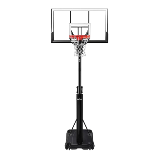
- Page 25 Assemble the Arena Slam™ Rim ASSEMBLE THE ARENA SLAM™ RIM 10. Thread the net (26) onto the rim (25). MOUNTING THE POLE PAD (May not be included with your system) 1. Fasten the pole pad to the front of the pole using the hook and loop straps. When finished, your system should look like the image below.
-
Page 26: Fill Assembled Unit For Use
Fill Assembled Unit for Use Fill Assembled Unit for Use Required Parts: Complete Unit Assembly: • Water or Sand WARNING • TWO CAPABLE ADULTS ARE REQUIRED FOR THIS PROCEDURE. FAILURE TO FOLLOW THIS WARNING COULD RESULT IN SERIOUS INJURY. • DO NOT LEAVE THE ASSEMBLY UNATTENDED WHEN EMPTY; IT MAY TIP OVER. •... - Page 27 Fill Assembled Unit for Use FILL ASSEMBLED UNIT FOR USE TO FILL WITH WATER: 1. Roll the completed assembly to desired location. 2. Tighten both base caps (23) and base cap gaskets (45) securely into place. 3. Fill the base with water (approx. 129 l / 34 gal).
-
Page 28: Operation
Operation Operation ADJUSTING THE HEIGHT 1. Squeeze the elevator trigger. 2. Lower or raise the handle to adjust the backboard height. MOVING THE UNIT 1. Lower the backboard height to the lowest position. 2. Grasp the oval pole and tilt system until the wheels of the base engage with the ground. 3. -
Page 29: Parts List
Parts List Parts List... - Page 30 Parts List Item Part No . Description Item Part No . Description 600336 Base, (Black) 108163 Pole Mount Bracket 10884401 Wheel Axle 208510 Bolt, Carriage, 5/16-18 × 4.25 in Long 266200 Wheel, 10 cm / 4 in 201683 Spacer 0.53 I.D. × 1.50 Long 901704 Top Pole Section - Black 208760...
- Page 31 801477 Cover, Spalding Backboard, 137 cm (54 in) 204007 Nut, Nylock, M4 × 0.7 THIS SPALDING PRODUCT IS DISTRIBUTED EXCLUSIVELY BY COSTCO AT THE FOLLOWING LOCATIONS: Distributed by: Costco Wholesale Canada Ltd.* Importado por: Costco Wholesale Australia Pty Ltd Costco Wholesale Corporation 415 W.
- Page 32 © Copyright 2022 by Russell Brands, LLC ATTENTION: CE PANNEAU ET CET ANNEAU NE Australian only - board warning www .Spalding .com SONT PAS CONÇUS POUR SUPPORTER UN JOUEUR SUSPENDU À L'ANNEAU OU AU FILET. LE NON-RESPECT DE CETTE MISE EN GARDE PEUT...
- Page 33 Número de modelo: ITM. / ART. 2622007 (se encuentra en la caja del producto) ESPAÑOL SISTEMA PORTÁTIL DE BALONCESTO Manual del propietario Teléfono gratuito del servicio al cliente EE. UU.: 1-800-558-5234 Canadá: 1-800-284-8339 Europa: +353 51 379777 Australia: 1300 367 582 www.spalding.com...
-
Page 34: Contenido
¡Llame al número telefónico GRATUITO de Servicio al Cliente que se indica en la primera página! EE. UU.: 1-800-558-5234 Canadá: 1-800-284-8339 Teléfono gratuito del servicio al cliente: Europa: +353 51 379777 Australia: 1300 367 582 Dirección postal: Spalding PO Box 90015 Bowling Green, KY 42102... -
Page 35: Garantía
Garantía Garantía Para obtener la información más reciente sobre la Garantía del Sistema de Baloncesto, visite www.Spalding.com o llame al Servicio al Cliente de Spalding al 1-800-558-5234. Para obtener la información sobre la Garantía de Spalding para Australia, visite www.spalding.com.au/warranty-information AUSTRALIA: Nuestros productos cuentan con garantías que no se pueden excluir bajo las Leyes del Consumidor de... -
Page 36: Comprobación Del Ajuste De Los Pernos
Comprobación del ajuste de los pernos de tolerancia estrecha Comprobación del ajuste de los pernos de tolerancia estrecha Para garantizar que el sistema del tablero ofrezca una calidad de juego óptima, se requiere una estrecha tolerancia del ajuste entre los componentes del elevador y los herrajes. Compruebe el ajuste de los pernos grandes en los orificios grandes de los tubos del elevador, los soportes del tablero y las placas triangulares. - Page 37 27 Soporte de montaje del poste (×1) negro (×2) negro (×4) Tubo, elevador vertical, Tubo, amortiguador de gas, 54 Montaje del amortiguador de gas (×1) amortiguador de gas (×2) brazos de la manija (×2) 56 Cubierta, Spalding (×1) 59 Manija, elevador de gas (×1)
- Page 38 Contenido del paquete HERRAJES DEL ELEVADOR ACCUGLIDE Núm . Perno, hexagonal, 1/2-13 x 6,5 pulg de largo (×2) KIT 3 – 208995 Núm . 13 Núm . 16 Núm . 40 203099Hex Locknut (Nylon Insert) 5/16-18 203100 NUT, HEX FLANGE, 5/16-18 Núm .
- Page 39 Contenido del paquete 42 Tubo del elevador, superior - negro (×2) HERRAJES DEL ELEVADOR (pieza a escala para la página) Núm . 43 Perno, hexagonal, 1/2-13 x 7 pulg de largo (×3) KIT 4 – 208889 Núm . 9 Núm . 14 Núm .
- Page 40 Contenido del paquete MONTAJE DEL ARO ARENA SLAM Núm . 32 Núm . 24 Núm . 47 Núm . 25 Núm . 26 24 Tapa, base (×1) 25 Aro (×1) 26 Red (×1) 32 Soporte, Slam Jam (×1) 47 Placa de cubierta, aro (×1) KIT 5 –...
-
Page 41: Herramientas Y Materiales Para El Montaje
Herramientas y materiales para el montaje Herramientas y materiales para el montaje NOTA En algunos pasos de la instalación puede ser necesario el uso de dos llaves, dos llaves de vaso o una combinación de ambas para mantener los pernos en su sitio mientras de aprietan las tuercas. Llave de vaso Extensión de llave Llave... -
Page 42: Vista General De Montaje
Vista general de montaje Vista general de montaje Tablero (Sección G) Aro (Sección H) Ajuste del elevador (Sección F) Puntales de soporte (Sección E) Poste (Sección A) Base (Secciones B, C, D, I) -
Page 43: Montaje De La Base
Montaje de la base Montaje de la base Piezas necesarias: Montaje completo de la base: • Kit 1 • Kit 2 • Tablero de madera de desecho • Llave de vaso o llave 1/2 pulg, 9/16 pulg MONTAJE DEL POSTE OVALADO 1. - Page 44 PRECAUCIÓN SI NO PUEDE CONSEGUIR UNA SUPERPOSICIÓN DE ENGANCHE MÍNIMA DE 9 CM (3,5 pulg), ¡¡PARE!! ¡NO CONTINÚE CON EL SIGUIENTE PASO! - LLAME AL SERVICIO AL CLIENTE DE SPALDING AL 1-800-558-5234 PARA RECIBIR AYUDA. 3. Alinee la sección superior del poste (4) con la sección intermedia del poste (5) y encájelas.
- Page 45 Montaje de la base COLOCACIÓN DE LAS RUEDAS EN LA BASE 1. Introduzca las ruedas (3) en cada soporte de las ruedas (19). 2. Introduzca el eje de las ruedas (2) a través de ambas ruedas (3) y soportes de las ruedas (19). Núm .
- Page 46 Montaje de la base COLOCACIÓN DE LOS PUNTALES EN LA BASE 1. Conecte el extremo plano de cada puntal del tanque (10) al poste ovalado utilizando el perno (11), las arandelas (12) y las tuercas (13). Núm . 13 Núm . 12 Núm .
-
Page 47: Montaje Del Elevador De
Montaje del elevador de AccuGlide™ Montaje del elevador de AccuGlide™ Piezas necesarias: Montaje completo del elevador de AccuGlide • Kit 3 • Llave de vaso o llave 1/2 pulg, 3/4 pulg MONTAJE DEL ELEVADOR DE ACCUGLIDE 1. Fije el soporte del montaje del poste (27) y el soporte de refuerzo (34) en los orificios de montaje del poste superior (4) utilizando Núm . - Page 48 Montaje del elevador de AccuGlide™ MONTAJE DEL ELEVADOR DE ACCUGLIDE 5. Deslice la cubierta superior (56) sobre el montaje del amortiguador de gas (54). NOTA Es posible que este paso haya sido completado previamente. Núm . 56 Núm . 54 6.
- Page 49 Montaje del elevador de AccuGlide™ MONTAJE DEL ELEVADOR DE ACCUGLIDE Etiqueta adhesiva de identificación Identification Sticker (PARTE SUPERIOR) (TOP) Núm . 52 Núm . 37 Núm . 59 (PARTE INFERIOR) (BOTTOM) 10. Inserte el perno (44) a través de los brazos de la manija (53), los tubos verticales (52) y el soporte del montaje de amortiguador de gas.
-
Page 50: Montaje Del Tablero
Montaje del tablero Montaje del tablero Piezas necesarias: Montaje completo del tablero: • Kit 4 • Llave de vaso o llave 7 mm, 9/16 pulg, 3/4 pulg • Caballete ADVERTENCIA SE REQUIEREN DOS PERSONAS PARA ESTE PROCEDIMIENTO. EL INCUMPLIMIENTO DE ESTA ADVERTENCIA PODRÍA OCASIONAR LESIONES GRAVES Y/O DAÑOS MATERIALES. - Page 51 Montaje del tablero MONTAJE DEL TABLERO 3. Fije los tubos superiores del elevador (42) a la sección del poste superior (4) utilizando el perno (43), el espaciador (20) y la tuerca (40). 4. Apriete con la mano. Orientación del tubo Elevator Tube Orientation del elevador...
- Page 52 Montaje del tablero MONTAJE DEL TABLERO 8. Coloque los tubos superiores e inferiores del elevador (41 y 42) a la parte posterior del tablero utilizando los espaciadores (20), los pernos (14), y las tuercas (9). Núm . 20 Núm . 20 Núm .
- Page 53 Montaje del tablero MONTAJE DEL TABLERO 10. Fije el gatillo (8) al montaje del amortiguador de gas (54) con el perno (58) y la tuerca (57). NOTA EL GATILLO QUEDARÁ SITUADO ENTRE LAS PLACAS DEL SOPORTE Y ENCIMA DEL PERNO (44). AL APRETAR EL GATILLO SE PODRÁ...
-
Page 54: Montaje Del Aro De Arena Slam
Montaje del aro de Arena Slam™ Montaje del aro de Arena Slam™ Piezas necesarias: Montaje completo del aro de Arena Slam • Kit 5 • Llave de vaso o llave 1/2 pulg, 3/4 pulg • Destornillador de estrella núm . 3 MONTAJE DEL ARO DE ARENA SLAM 1. - Page 55 Montaje del aro de Arena Slam™ MONTAJE DEL ARO DE ARENA SLAM 4. Fije firmemente el aro (25) en el soporte slam jam (32). Deje que el perno en T (33) se deslice a través del orificio central en el aro (25). Núm .
- Page 56 Montaje del aro de Arena Slam™ MONTAJE DEL ARO DE ARENA SLAM 7. Instale la tuerca especial (36) y la arandela (35) en el perno en T (33). Núm . 36 Núm . 35 Núm . 33 8. Apriete la tuerca (36) hasta 3 mm (1/8 in) de las roscas del perno en el extremo Núm .
- Page 57 Montaje del aro de Arena Slam™ MONTAJE DEL ARO DE ARENA SLAM 10. Enganche la red (26) en el aro (25). Núm. 26 Núm. 25 Núm. 26 Núm. 25 MONTAJE DE LA ALMOHADILLA DEL POSTE (Puede no estar incluida en su sistema) 1.
-
Page 58: Llenado De La Unidad Montada Para Su Uso
Llenado de la unidad montada para su uso Llenado de la unidad montada para su uso Piezas necesarias: Montaje completo de la unidad: • Agua o Arena ADVERTENCIA • SE REQUIEREN DOS ADULTOS CAPACES PARA ESTE PROCEDIMIENTO. EL INCUMPLIMIENTO DE ESTA ADVERTENCIA PODRÍA OCASIONAR LESIONES GRAVES Y/O DAÑOS MATERIALES. - Page 59 Llenado de la unidad montada para su uso LLENADO DE LA UNIDAD MONTADA PARA SU USO LLENADO CON AGUA: 1. Mueva el conjunto completado a la ubicación deseada. 2. Apriete las dos tapas de la base (23) y las juntas de la tapa de la base (45) firmemente en su sitio.
-
Page 60: Funcionamiento
Funcionamiento Funcionamiento AJUSTE DE LA ALTURA 1. Apriete el gatillo del elevador. 2. Suba o baje la manija para justar la altura del tablero. Núm . 8 Núm. 60 MOVIMIENTO DE LA UNIDAD 1. Baje la altura del tablero hasta la posición más baja. 2. -
Page 61: Lista De Piezas
Lista de piezas Lista de piezas Núm . 9 Núm . 20 Núm . 22 Núm . 42 Núm . 40 Núm . 20 Núm . 9 Núm . 60 Núm . 42 Núm . 20 Núm . 43 Núm . 14 Núm . - Page 62 Lista de piezas Art . Cant . Núm . de Descripción Art . Cant . Núm . de Descripción pieza pieza 600336 Base, (negra) 108163 Soporte de montaje del poste Perno, carrocería, 5/16-18 x 4,25 10884401 Eje de las ruedas 208510 pulg de largo Espaciador d.
- Page 63 Cubierta, Spalding Tablero, 137 cm (54 in) 204007 Tuerca, Nylock, M4 × 0,7 COSTCO ES EL ÚNICO DISTRIBUIDOR DE ESTE PRODUCTO DE SPALDING EN LAS SIGUIENTES UBICACIONES: Distributed by: Costco Wholesale Canada Ltd.* Importado por: Costco Wholesale Australia Pty Ltd Costco Wholesale Corporation 415 W.
- Page 64 French only - board warning MISE EN GARDE : ONT PAS CONÇUS POUR SUPPORTER UN © Copyright 2022 de Russell Brands, LLC ESPECT DE CETTE MISE EN GARDE PEUT www .Spalding .com NER DES BLESSURES CORPORELLES ET / OU DES DOMMAGES MATÉRIELS.
- Page 65 Numéro de modèle : ITM. / ART. 2622007 (sur la boîte du produit) FRANÇAIS SYSTÈME DE BASKET-BALL TRANSPORTABLE Guide d’utilisation Numéro vert du service client États-Unis : 1-800-558-5234 Canada : 1-800-284-8339 Europe : +353 51 379777 Australie : 1300 367 582 www.spalding.com...
-
Page 66: Avant De Commencer
Courriel : warrantyservice@custserv.fotlinc.com États-Unis : 1-800-558-5234 Canada : 1-800-284-8339 Numéro vert du service client : Europe : +353 51 379777 Australie : 1300 367 582 Adresse postale : Spalding PO Box 90015 Bowling Green, KY 42102... -
Page 67: Garantie
Pour les toutes dernières informations concernant la garantie du système de basket-ball, aller sur www.Spalding.com ou appeler le service client Spalding au 1-800-558-5234. Pour les informations concernant la garantie du Australie, aller sur www.spalding.com.au/warranty-information AUSTRALIE: Nos articles sont offerts avec des garanties qui ne peuvent connaître d'exclusions au regard de la loi australienne sur la protection des consommateurs. -
Page 68: Test D'ajustement Des Vis À Tolérance Précise
Test d’ajustement des vis à tolérance précise Test d’ajustement des vis à tolérance précise Afin d’assurer une jouabilité optimale du système de panneau, un ajustement précis des tolérances entre les composants du système de levage et la visserie est requis. Faites un essai d’ajustement des grosses vis dans les gros trous des tubes du système de levage, des supports du panneau et des plaques triangulaires. - Page 69 27 Support de montage du poteau (×1) noir (×2) noir (×4) Tube, système de levage vertical, Tube, vérin à gaz, bras de 54 Ensemble vérin à gaz (×1) vérin à gaz (×2) poignée (×2) 56 Protection, Spalding (×1) 59 Poignée, vérin à gaz (×1)
- Page 70 Contenu du paquet VISSERIE DU DISPOSITIF DE LEVAGE ACCUGLIDE 44 Vis hexagonale, 1/2-13 x 6,5 po de long (×2) KIT 3 – 208995 203099Hex Locknut (Nylon Insert) 5/16-18 203100 NUT, HEX FLANGE, 5/16-18 Écrou à bride hexagonale, Vis hexagonale, 5/16-18 x 1,75 po 13 Écrou, nyloc, 5/16-18 (×1) 5/16-18 (×2) de long (×1)
- Page 71 Contenu du paquet VISSERIE DU PANNEAU (échelle des pièces adaptée à la page) Vis hexagonale, 1/2-13 x 7 po de long (×3) KIT 4 – 208889 Vis hexagonale, 3/8-16 x 2,0 de Cale d’espacement, Écrou, nyloc, 3/8-16 (×4) long (×4) D.I.
- Page 72 Contenu du paquet ASSEMBLAGE DE L’ANNEAU ARENA SLAM 24 Capuchon de la base (×1) 25 Anneau (×1) 26 Filet (×1) 32 Support, Slam Jam (×1) 47 Plaque de protection, anneau (×1) KIT 5 – 208788 203100 NUT, HEX FLANGE, 5/16-18 Écrou à...
-
Page 73: Outils Et Matériel D'assemblage
Outils et matériel d’assemblage Outils et matériel d’assemblage REMARQUE Certaines étapes de l’installation peuvent nécessiter deux clés à douille et deux clés, ou une combinaison des deux, pour maintenir les boulons en place lors du serrage des écrous. ET/OU Clé à douille Extension de clé... -
Page 74: Présentation De L'assemblage
Présentation de l’assemblage Présentation de l’assemblage Panneau (Section G) Anneau (Section H) Réglage du système de levage (Section F) Poteau (Section A) Vérins de support (Section E) Poteau (Section A) Base (Section B, C, D, I) -
Page 75: Assemblage De La Base
Assemblage de la base Assemblage de la base Pièces requises : Assemblage de la base terminé : • Kit 1 • Kit 2 • Chute de bois • Clé à douille ou clé 1/2 po, 9/16 po ASSEMBLAGE DU POTEAU OVALE 1. - Page 76 ARRÊTEZ IMMÉDIATEMENT ! NE PASSEZ PAS À L’ÉTAPE SUIVANTE ! - APPELEZ LE SERVICE CLIENT SPALDING AU 1-800-558-5234 ET DEMANDEZ DE L’AIDE. 3. Aligner la section de poteau supérieure (4) sur la section de poteau centrale (5), puis les glisser l‘une dans l‘autre.
- Page 77 Assemblage de la base INSTALLATION DES ROUES SUR LA BASE 1. Insérer les roues (3) à l’intérieur de chaque support de roue (19). 2. Insérer l’essieu (2) à travers les deux roues (3) et supports de roue (19). 3. Insérer l’assemblage de l’essieu sous la base (1).
- Page 78 Assemblage de la base INSTALLATION DES VÉRINS SUR LA BASE 1. Attacher l’extrémité plate de chaque vérin de réservoir (10) au poteau ovale à l’aide de la vis (11), des rondelles (12), des cales d’espacement (46) et des écrous (13). AVERTISSEMENT SERRER LA VIS (11) DANS LE CONTRE-ÉCROU (13) JUSQU’À...
-
Page 79: Assemblage Du Dispositif De Levage
Assemblage du dispositif de levage AccuGlide™ Assemblage du dispositif de levage AccuGlide™ Pièces requises : Dispositif de levage AccuGlide terminé : • Kit 3 • Clé à douille ou clé ASSEMBLAGE DU DISPOSITIF DE LEVAGE ACCUGLIDE 1. Fixer le support de montage du poteau (27) et le support de renfort (34) dans les trous de montage du poteau supérieur (4) - Page 80 Assemblage du dispositif de levage AccuGlide™ ASSEMBLAGE DU DISPOSITIF DE LEVAGE ACCUGLIDE 5. Faire coulisser la protection (56) sur l’assemblage du vérin à gaz (54). REMARQUE Cette étape est parfois déjà effectuée à l'usine. 6. Fixer le vérin à gaz (54) au support de montage du poteau (27) à l’aide de la vis (18) et de l’écrou (13).
- Page 81 Assemblage du dispositif de levage AccuGlide™ ASSEMBLAGE DU DISPOSITIF DE LEVAGE ACCUGLIDE 10. Insérer la vis (44) dans les bras de poignée (53), les tubes verticaux (52) et le support de l'assemblage du vérin à gaz. Fixer à l’aide de l’écrou (40). AVERTISSEMENT SERRER LA VIS (44) DANS LE CONTRE-ÉCROU (40) JUSQU’À...
-
Page 82: Assemblage Du Panneau
Assemblage du panneau Assemblage du panneau Pièces requises : Assemblage du panneau terminé : • Kit 4 • Clé à douille ou clé • Tréteau AVERTISSEMENT DEUX PERSONNES SONT REQUISES POUR CETTE PROCÉDURE. LE NON-RESPECT DE CET AVERTISSEMENT PEUT ENTRAÎNER DES BLESSURES GRAVES ET/OU DES DOMMAGES MATÉRIELS. ASSEMBLAGE DU PANNEAU 1. - Page 83 Assemblage du panneau ASSEMBLAGE DU PANNEAU 3. Fixer les tubes supérieurs du système de levage (42) à la section de poteau supérieure (4) à l’aide de la vis (43), de la cale d’espacement (20) et de l’écrou (40). 4. Serrer à la main. Orientation du tube du Elevator Tube systeme de lavage...
- Page 84 Assemblage du panneau ASSEMBLAGE DU PANNEAU 8. Fixer les tubes inférieurs et supérieurs du système de levage (41 et 42) à l’arrière du panneau à l’aide des cales d’espacement en métal (14), des vis (8) et des écrous (9). 9. Serrer fermement toutes les vis de cette section. AVERTISSEMENT NE PAS LAISSER L'ASSEMBLAGE SANS SURVEILLANCE LORSQU'IL EST VIDE, CAR IL POURRAIT BASCULER.
- Page 85 Assemblage du panneau ASSEMBLAGE DU PANNEAU 10. Fixer le déclencheur (8) à l’assemblage du vérin à gaz (54) en utilisant une vis (58) et un écrou (57). REMARQUE LE DÉCLENCHEUR SERA PLACÉ ENTRE LES PLAQUES DU SUPPORT ET AU-DESSUS DE LA VIS (44). APPUYER SUR LE DÉCLENCHEUR PERMETTRA DE RÉGLER LA HAUTEUR DE L’ANNEAU.
-
Page 86: Assemblage De L'anneau Arena
Assemblage de l’anneau Arena Slam™ Assemblage de l’anneau Arena Slam™ Pièces requises : Anneau Arena Slam terminé : • Kit 5 • Clé à douille ou clé • Tournevis cruciforme n° 3 ASSEMBLAGE DE L’ANNEAU ARENA SLAM 1. Décoller et retirer le film protecteur de la face avant du panneau. - Page 87 Assemblage de l’anneau Arena Slam™ ASSEMBLAGE DE L’ANNEAU ARENA SLAM 4. Bien installer l’anneau (25) dans le support du Slam Jam (32). Laisser glisser la vis en T (33) à travers le trou central de l’anneau (25). 5. Installer le support de renfort (31) sur la vis en T (33). 6.
- Page 88 Assemblage de l’anneau Arena Slam™ ASSEMBLAGE DE L’ANNEAU ARENA SLAM 7. Installer l’écrou spécial (36) et la rondelle (35) sur la vis en T (33). 8. Serrer l’écrou (36) jusqu’à ce que 3 mm (1/8 de pouce) du pas de vis sur l’extrémité...
- Page 89 Assemblage de l’anneau Arena Slam™ ASSEMBLAGE DE L’ANNEAU ARENA SLAM 10. Installer le filet (26) sur l’anneau (25). MONTAGE DE LA MOUSSE DE PROTECTION DU POTEAU (Pas systématiquement fourni avec votre système) 1. Fixez la mousse de protection à l’avant du poteau en utilisant le crochet et les sangles. Lorsque vous aurez terminé, votre système devrait être similaire à...
-
Page 90: Remplissage De L'ensemble Avant Utilisation
Remplissage de l’ensemble avant utilisation Remplissage de l’ensemble avant utilisation Pièces requises : Assemblage au complet : • Eau ou Sable AVERTISSEMENT • CETTE PROCÉDURE DOIT ÊTRE RÉALISÉE PAR DEUX ADULTES APTES. LE NON-RESPECT DE CET AVERTISSEMENT PEUT ENTRAÎNER DES BLESSURES GRAVES. •... - Page 91 Remplissage de l’ensemble avant utilisation REMPLISSAGE DE L’ENSEMBLE AVANT UTILISATION POUR REMPLIR D’EAU : 1. Faire rouler l’assemblage achevé à l’emplacement souhaité. 2. Bien serrer les deux bouchons de la base (23) et les joints de bouchon de la base (45) en place.
-
Page 92: Utilisation
Utilisation Utilisation RÉGLAGE DE LA HAUTEUR 1. Serrer le déclencheur du système de levage. 2. Abaisser ou relever la poignée pour ajuster la hauteur du panneau. DÉPLACEMENT DE L’ENSEMBLE 1. Abaisser le panneau à son réglage le plus bas. 2. Saisir le poteau ovale et incliner le système jusqu’à ce que les roues de la base touchent bien le sol. 3. -
Page 93: Liste Des Pièces
Liste des pièces Liste des pièces... - Page 94 Liste des pièces Article Qté Nº de pièce Description Article Qté Nº de pièce Description 600336 Base (noire) 108163 Support de montage du poteau Vis de carrosserie, 5/16-18 x 10884401 Essieu de roue 208510 4,25 po de long Cale d’espacement, 0,53 de D.I. x 266200 Roue, 4 po 201683...
- Page 95 801477 Protection, Spalding Panneau, 137 cm (54 po) 204007 Écrou, nyloc, M4 x 0,7 CE PRODUIT SPALDING EST VENDU EXCLUSIVEMENT DANS CES MAGASINS COSTCO : Distributed by: Costco Wholesale Canada Ltd.* Importado por: Costco Wholesale Australia Pty Ltd Costco Wholesale Corporation 415 W.
- Page 96 ENTRAÎNER DES BLESSURES CORPORELLES ET / KANN ZU KÖRPERVERLETZUNGEN UND / OU DES DOMMAGES MATÉRIELS. ODER SACHSCHÄDEN FÜHREN. © Copyright 2022 by Russell Brands, LLC Spanish only - board warning www .Spalding .com PRECAUCIÓN: EL TABLERO Y EL ARO NO ESTÁN DISEÑADOS...
Need help?
Do you have a question about the 2622007 and is the answer not in the manual?
Questions and answers