Table of Contents
Advertisement
Quick Links
.
Write Model Number From Box Here:
© COPYRIGHT 2021 by Russel Brands, LLC
In-Ground Basketball System
Owners Manual
Toll-Free Customer Service Number for U.S: 1-800-558-5234,
For Canada: 1-800-284-8339,
For Europe: +353 51 379777,
For Australia: 1-300-367-582
This manual, accompanied by sales receipt,
should be saved and kept on hand as a
convenient reference, as it contains important
1
English
WARNING!
READ AND UNDERSTAND
OPERATOR'S MANUAL
BEFORE USING THIS UNIT.
FAILURE TO FOLLOW
OPERATING
COULD RESULT IN INJURY
OR DAMAGE TO PROPERTY.
information about your model.
2/21
ID# M8891201
INSTRUCTIONS
Advertisement
Table of Contents

Subscribe to Our Youtube Channel
Related Manuals for SPALDING 881042


Summary of Contents for SPALDING 881042
- Page 1 English In-Ground Basketball System Owners Manual WARNING! READ AND UNDERSTAND OPERATOR’S MANUAL BEFORE USING THIS UNIT. FAILURE TO FOLLOW OPERATING INSTRUCTIONS COULD RESULT IN INJURY OR DAMAGE TO PROPERTY. Write Model Number From Box Here: This manual, accompanied by sales receipt, should be saved and kept on hand as a convenient reference, as it contains important information about your model.
- Page 2 ALL basketball systems, including those used for DISPLAYS, MUST be assembled and installed according to instructions. Failure to follow instructions could result in SERIOUS INJURY. It is NOT acceptable to devise a makeshift support system. Email: warrantyservice@custserv.fotlinc.com Spalding PO Box 90015 Bowling Green, KY 42102...
- Page 3 Sistema de Baloncesto Garantía Para obtener la última información sobre la garantía del Sistema de Baloncesto Visite el sitio web de Spalding Basketball en www.Spalding.com Póngase en contacto con el servicio al cliente de Spalding llamando al teléfono 1-800-558-5234 05/2013...
-
Page 4: Height Adjustment
REQUIRED TOOLS AND MATERIALS: HEIGHT ADJUSTMENT • 2 Capable Adults TO ADJUST BACKBOARD: 1. Grasp handle and squeeze trigger. • Tape Measure 2. Raise or lower to desired height. 3. Release trigger. • Wood Board (scrap) 500065IG 05/20 • Sawhorse or Support Table •... -
Page 5: Safety Instructions
TEST-FIT CLOSE TOLERANCE BOLTS To ensure optimal playability of backboard system, a close tolerance fit between the elevator components and hardware is required. Test-fit large bolts into large holes of elevator tubes, backboard brackets, and triangle plates. Carefully rock them in a circular motion to ream out any excess paint from holes if necessary. NOTE: Not all items pictured are included with every model. -
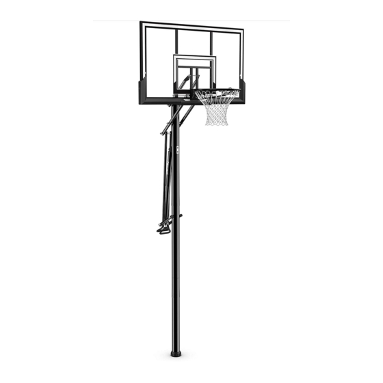
Page 6: Front View
Get to know the basic parts of your basketball system... FRONT VIEW BACKBOARD ELEVATOR ADJUSTMENT POLE BASE NOTE: BOARD STYLE WILL VARY... - Page 7 Bolt, Hex, 1/2-13 x 8” Long 900033 Bracket, Slam Jam 204007 Nut, Nylock, M4 x 0.7 206048 Bolt, Tee, 3/8-16, 3.25” Long 1 20279502 Label, Spalding 901527 Tube, Gas Strut, Handle Arms 203063 Nut, Ny-lock, 3/8-16 220579 Spacer, 0.51 I.D. x 5.0 Long...
- Page 8 HARDWARE IDENTIFIER (BOLTS AND SCREWS) #16 (2) #20 (1) #28 (1) #12 (1) #38 (4) 201596 Screw 1/4 x 1. 202871 - SCREW HEX WASHR HD TAP SLOTTED 1/4 X 3/4 #43 (2) #48 (2) #50 (4) 208668 #51 (2) #54 (4) #23 (2)
- Page 9 HARDWARE IDENTIFIER (NUTS AND WASHERS) #55 (1) #13 (6) #37 (1) 203100 NUT, HEX FLANGE, 5/16-18 #24 (1) #18 (6) #41 (1) #49 (6) 203099Hex Locknut (Nylon Insert) 5/16-18 HARDWARE IDENTIFIER (PLASTIC SPACERS, CAPS, CLIPS AND OTHER) #52 (4) #25 (1) #19 (6) #53 (1) #206311...
-
Page 10: Section A: Assemble The Pole
SECTION A: ASSEMBLE THE POLE This is what your system will look like when you’ve finished this section. ITEMS REQUIRED FOR THIS SECTION (2) 1/2”, and (2) 9/16” Wrenches AND/OR (2) Socket Wrenches and Sockets 1/2” 9/16” Wood Board (scrap) Hammer or Mallet... - Page 11 Correctly identify each pole section and mark 5” (13 cm) from top of middle pole section (2) and top of bottom pole section (3) ends with tape or marker. WARNING! CONTACT UTILITIES BEFORE DIGGING. 5” (13 cm) XG02.EPS Line NOTE: BOTTOM Maximum distance from edge of hole to edge of playing surface 6”...
- Page 12 Snap the two halves of ground sleeve (4) together. Insert and secure the bottom pole section (3) into the ground sleeve (4) by tightening the ground sleeve cap (5). NOTE: Flared end goes inside ground sleeve. Fill the hole approximately 1/3 full with the mixed concrete.
-
Page 13: Side View
Insert the ground sleeve assembly and center in the hole (FIG. A). FIG. A NOTE: Leave 1” below flange exposed for drainage hill. SIDE VIEW PLAYING SURFACE FLANGE 1" (2.54 cm) IMPORTANT! NOTE THE POSITION OF THE FLANGE IMPORTANT! CONTINUE ON TO NEXT STEP. DO NOT WAIT FOR CONCRETE TO CURE. Fill the hole completely with concrete. - Page 14 Tamp down the concrete to release air pockets and build the drainage hill. Level the pole section in all directions several times while the concrete is curing. NOTE A: SIDE VIEW Make a reference mark here for anti-skid tape.. NOTE B: DRAINAGE HILL Keep flange pushed down to 1"...
- Page 15 Stack and bounce the bottom (3) and middle (2) pole sections together. Bounce the pole sections together until middle pole (2) moves to the 3 1/2” (9 cm) mark you made previously on bottom pole (3). IMPORTANT! POLE SECTIONS SHOULD HAVE A 3-1/2”...
- Page 16 Stack and bounce the top pole (1) onto middle (2) pole sections together. Bounce the pole sections together until middle pole (2) moves to the 3 1/2” (9 cm) mark you made previously. IMPORTANT! POLE SECTIONS SHOULD HAVE A 3-1/2” (9 CM) MINIMUM OVERLAP. 3-1/2”...
-
Page 17: Section B: Attach The Backboard And Gas Strut
SECTION B: ATTACH THE BACKBOARD AND GAS STRUT This is what your system will look like when ITEMS REQUIRED FOR THIS SECTION you’ve finished this section. (2) 7mm, (2) 1/2”, (2) 9/16” and (2) 3/4” Wrenches AND/OR (2) Socket Wrenches and Sockets 1/2”... -
Page 18: Front Side
Install the lift bracket (22) and reinforcement bracket (17) with the carriage bolts (16) in the top pole (1) mounting holes as shown. Tighten the flange nuts (13) completely. FRONT SIDE Install the gas strut handle arm tubes (29) to the middle pole (2) using the hex bolt (23) and nylock nut (18) as shown. - Page 19 Slide the top cover (8) over the gas strut assembly (21) as shown below. Attach the gas strut assembly (21) using the bolt (20) and nut (24) to the pole mount bracket (22) as shown. Identify and orient the vertical connecting tubes (36) according to the identification stickers and assemble to the handle (35).
- Page 20 Insert the bolt (23) through the handle arms (29), vertical tubes (36), and gas strut assembly bracket as shown. Secure using the nut (18) as shown. WARNING! TIGHTEN BOLT (23) IN LOCK NUT (18) UNTIL FLUSH (EVEN) WITH LOCK NUT’S OUTER EDGE.
-
Page 21: Section C: Assemble The Elevator Tubes To Backboard
SECTION C: ASSEMBLE THE ELEVATOR TUBES TO BACKBOARD This is what your system will look like when you’ve finished this section. TOOLS REQUIRED FOR THIS SECTION AND/OR (2) 1/2” and (2) 9/16” and (2) 3/4” Wrenches 3/4” 1/2” 9/16” (2) Socket Wrenches and Sockets... - Page 22 Identify the elevator tubes (14 and 15). Upper Elevator Tube Lower Elevator Tube Toward Pole Toward Board...
- Page 23 Attach the lower elevator tubes (15) to the backboard frame using the spacers (52), bolts (51), and nuts (57) as shown. Insert the t-bolt (28) through the slam jam bracket (27) as shown. Secure the slam jam bracket (27) to backboard using the bolts (38) and nuts (13) as shown.
- Page 24 Attach the upper elevator tubes (14) to backboard frame using spacers (52), bolt (51), and nut (57) as shown.
- Page 25 Install Board Pads to Backboard With the board still on saw horses or a support table: Attach the left (44) and right (45) pad sections to board using the screws (50) and washers (49) as shown. Using the holes which line up for your board size, attach the center pad section (46) to the left and right sections and board using screws (48) and washers (49) as shown.
- Page 26 Support the pole on a sawhorse. Attach the upper and lower elevator tubes (14 and 15) to the upper pole section (1) using the bolts (54), spacers (19), and nuts (18) as shown. Attach the lower elevator tubes (14) to the gas strut vertical elevator tubes (36) using the bolt (54), spacers (52, 19), and nut (18) as shown Securely tighten all the bolts...
- Page 27 Fasten the trigger (7) to the gas strut assembly (21) by using the bolt (12) and nut (55). NOTE: THE TRIGGER WILL BE BETWEEN THE PLATES OF THE BRACKET AND ABOVE THE BOLT (54). SQUEEZING THE TRIGGER WILL ALLOW THE RIM HEIGHT TO BE ADJUSTED.
- Page 28 Install Pro Slam Rim to Backboard A. Fit the rim (39) securely into the bracket (27) as shown. Allow the t-bolt (28) to slip through the center hole in the rim (39). NOTE: B. Install the reinforcement bracket (32) onto the t-bolt (28) as shown.
-
Page 29: Outside View
RIM COVER ATTACHMENT Install cover (42) over spring return mechanism using screws (43) as shown. NOTE: Cover plate (42) will fit INSIDE back bracket. NET INSTALLATION Install net (40) onto rim (39). OUTSIDE VIEW... -
Page 30: Section D: Attach The Backboard And Elevator Assembly To Pole System
SECTION D: ATTACH THE BACKBOARD AND ELEVATOR ASSEMBLY TO POLE SYSTEM This is what your system will look like when you’ve finished this section. CONCRETE TOOLS REQUIRED FOR THIS SECTION Concrete Container to Mix AND/OR 3/4” (2) 3/4” Wrenches (2) Socket Wrenches and Sockets... - Page 31 Apply the height adjustment and moving label (34) to the front of the pole as shown. HEIGHT ADJUSTMENT TO ADJUST BACKBOARD: 1. Grasp handle and squeeze trigger. 2. Raise or lower to desired height. 3. Release trigger. 500065IG 05/20 WARNING! DO NOT ALLOW CHILDREN TO ADJUST HEIGHT.
- Page 32 Assemble the rebar centering clips (10) near the top and bottom of rebar (9) as shown. 2” 3”...
- Page 33 Completely seal the hole at the bottom of the bottom pole with heavy-duty tape (not included) to retain the rebar (9) and concrete inside. Mix the concrete (approximately 100 lbs. (45.4 kg)) and fill the pole 1” - 2” (2.54 - 5.0 cm) below the bottom elevator hole on top pole section (1) as shown.
-
Page 34: Section E: Upright, Secure And Use Pole System
SECTION E: UPRIGHT, SECURE AND USE POLE SYSTEM This is what your system will look like when you’ve finished this section. TOOLS REQUIRED FOR THIS SECTION Wedge Hammer... - Page 35 After the concrete has cured, remove the tape, install the pole cap (11), and fit the pole assembly into the sleeve (4). WARNING! TWO CAPABLE ADULTS REQUIRED FOR THIS PROCEDURE. FAILURE TO FOLLOW THIS WARNING COULD RESULT IN SERIOUS INJURY AND/OR PROPERTY DAMAGE.
Need help?
Do you have a question about the 881042 and is the answer not in the manual?
Questions and answers