Advertisement
Quick Links
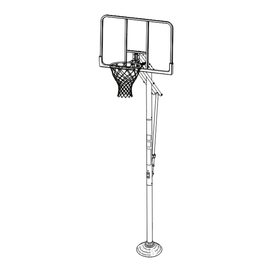
Inground System
Owners Manual
Système de poteau carré
Manuel de l'utilisateur
This manual, accompanied by sales receipt, should be saved and kept on hand as a convenient reference, as it
Ce manuel, accompagné du justificatif d'achat, devra être conservé pour référence ultérieure, dans la mesure où il
Write Model Number
From Box Here:
Inscrivez ici le numéro de
modèle qui apparaît sur la
boîte:
Toll-Free Customer Service Number for U.S: 1-800-558-5234, For Canada: 1-800-284-8339,
For Europe: 00 800 555 85234 (Sweden: 009 555 85234), For Australia: 1300 367 582
Numéro vert du Service clientèle - États-Unis: 1-800-558-5234, Canada: 1-800-284-8339,
Europe: 00 800 555 85234 (Suède: 009 555 85234), Australie: 1300 367 582
© COPYRIGHT 2019 by SPALDING
WARNING!
AVERTISSEMENT!
READ AND UNDERSTAND OPERATOR'S
MANUAL BEFORE USING THIS UNIT.
FAILURE TO FOLLOW OPERATING
INSTRUCTIONS COULD RESULT IN
INJURY OR DAMAGE TO PROPERTY.
LISEZ LE MODE D'EMPLOI
AVANT D'UTILISER CE SYSTÈME
SOUS PEINE D'ENCOURIR DES
BLESSURES OU DES DÉGÂTS
MATÉRIELS..
Adult Assembly Required.
Assemblage exclusivement réservé à un adulte.
contains important information about your model.
contient des informations importantes sur votre modèle.
• Two (2) Capable Adults
• Deux (2) adultes capables
• Carpenter's Level
• Niveau à bulle
• 15' Tape Measure
• Mètre de 4,5 m
• Shovel & Post Hole Digger
• Pelle et bêchet arière
• Wood Board (scrap)
• Planche en bois (chute)
• Sawhorse or Support Table
• Chevalet de sciage ou table
• Wedge
• Cale
Internet Address: www.spalding.com
Adresse Internet: www.spalding.com www.spalding.com.au
REQUIRED TOOLS AND MATERIALS:
OUTILS ET MATÉRIEL REQUIS:
• Hammer
• Marteau
• Stepladder 8 ft. (2.4 m)
• Escabeau de 2,4 m
• Safety Goggles
• Lunettes de sécurité
• Heavy Duty Tape
• Ruban extra-fort
• (2 each) Wrenches and/or Socket Wrenches and
Sockets (Deep-Well Sockets are Recommended).
• (2) Clés, (2) Clés à douilles et douilles. Extension
de douille
1/2"
9/16"
3/4"
www.spalding.com.au
1
CONCRETE
•
BÉTON
245 KG.
540 LBS.
• Container to Mix
• Récipient pour mélanger
• Optional: Large & Small
Adjustable Wrenches
• Facultatif: petites et
grandes clés anglaises
1/2"
9/16"
3/4"
10/18
ID# M881041
Advertisement

Related Manuals for SPALDING Basketball System


Summary of Contents for SPALDING Basketball System
- Page 1 For Europe: 00 800 555 85234 (Sweden: 009 555 85234), For Australia: 1300 367 582 Internet Address: www.spalding.com www.spalding.com.au Numéro vert du Service clientèle - États-Unis: 1-800-558-5234, Canada: 1-800-284-8339, Europe: 00 800 555 85234 (Suède: 009 555 85234), Australie: 1300 367 582 Adresse Internet: www.spalding.com www.spalding.com.au 10/18 ID# M881041 © COPYRIGHT 2019 by SPALDING...
- Page 2 Europa: 00 800 555 85234 (Schweden: 009 555 85234), für Australien: 1300 367 582 Internet-Adresse: www.spalding.com www.spalding.com.au Número telefónico sin costo del Departamento de Servicio al Cliente en EE.UU.: 1-800-558-5234, Para Canadá: 1-800-284-8339, Para Europa: 00 800 555 85234 (Suecia: 009 555 85234), Para Australia: 1300 367 582 Dirección en Internet: www.spalding.com www.spalding.com.au...
- Page 3 BEFORE YOU START! AVANT DE COMMENCER! VORBEREITENDE MASSNAHMEN ¡ANTES DE COMENZAR! Fragen oder fehlende Teile? HALT! Gehen Sie NICHT zum Laden zurück! Rufen Sie die GEBÜHRENFREIE Telefonnummer (in den USA und Kanada) auf der Vorderseite an! Des questions ou des ¿Tiene preguntas o le faltan piezas? pièces manquantes? STOP!
- Page 4 AVERTI S SEMENT Lisez les avertissements indiqués ci-dessous avant d'utiliser ce produit. MUNSELL NOTATION Value Chroma sous peine d'encourir des blessures 5.0 YR 6.0/15 graves et/ou des dégâts matériels. Equiv. CIE Data (Y%) Le propriétaire du système doit s’assurer que tous les 30.05 0.5510 0.4214...
- Page 7 KÖNNEN ZU DEREN PLÖTZLICHEM BRUCH FÜHREN. WENN DIE KORBWAND VOR ODER NACH DEM ZUSAMMENBAU IN JEGLICHER WEISE BESCHÄDIGT WIRD, RUFEN SIE DIE FOLGENDE GEBÜHRENFREIE TELEFONNUMMER AN: Innerhalb der USA: 1-800-558-5234; innerhalb KANADAS: 1-800-284-8339; http://www.spalding.com ¡ADVERTENCIA! SI SU SISTEMA ESTÁ EQUIPADO CON UN RESPALDO DE ACRÍLICO, EXAMINE EL RESPALDO PARA VERIFICAR QUE NO HAYA SUFRIDO DA—OS DURANTE EL TRANSPORTE.
- Page 8 Sistema de baloncesto Garantía de dueños Para la última información de garantía del sistema de baloncesto Por favor visite el sitio web de Spalding Basketball en www.Spalding.com 1-800-558-5234 Póngase en contacto con servicio al cliente de Spalding en teléfono #...
- Page 9 Get to know the basic parts of your basketball system... Apprenez à connaître les composants de base de votre système de basket-ball... Machen Sie sich mit den wichtigsten Teilen Ihres Basketballsystems vertraut… Conozca las piezas básicas de su sistema de baloncesto…...
- Page 10 * You may have extra parts with this model. NOTE Hardware kit is designed for more than one style of basketball system. In some models not all hardware will be used. Some models may not include all hardware listed in Parts List.
- Page 11 LISTE DES PIÈCES - Voir légende Légende Qté No de réf. Description Légende Qté No de réf. Description Tube du système élévateur, supérieur 900634 Section de poteau supérieure 901675 901035 Section de poteau centrale 901676 Tube du système élévateur, inférieur 900641 Section de poteau inférieure 208892...
- Page 12 TEILELISTE - Siehe Teileschlüssel Nr. Anz. Teile-Nr. Beschreibung Nr. Anz. Teile-Nr. Beschreibung 900634 Oberes Stangenteil 901676 Unteres Verlängerungsrohr 901035 Mittleres Stangenteil 208892 Sechskantkopfschraube, 5/16-18 x 1.625 900641 Unteres Stangenteil Zoll Länge 202800 Bodenmuffenhälfte 206048 T-Nutenschraube, 3/8-16 x 3.25 Zoll Länge 202801 Bodenmuffenabdeckung 900033...
- Page 13 LISTA DE PIEZAS - Vea el identificador de herraje Artículo Cant. Pieza N.º Descripción Artículo Cant. Pieza N.º Descripción 900634 Sección superior del poste 204838 Resorte, elevador 901675 Tubos elevadores, superiores 901035 Sección media del poste 900641 Sección inferior del poste 901676 Tubo elevador, inferior 202800 Mitad de la manga del piso 208892 Perno, cabeza hexagonal, 5/16-18 x...
- Page 14 HARDWARE IDENTIFIER (BOLTS & SCREWS) IDENTIFICATION DES PIÈCES (BOULONS & VIS) BEFESTIGUNGSTEILESCHLÜSSEL (BOLZEN UND SCHRAUBEN) IDENTIFICADOR DE HERRAJE (PERNOS Y TORNILLOS) #13 (2) #18 (1) #27 (4) Item #20 (5) #28 (1) Item #23 (2) #7 (2) HARDWARE IDENTIFIER (NUTS & WASHERS) IDENTIFICATION DES PIÈCES (ÉCROUS &...
- Page 15 HARDWARE IDENTIFIER (PLASTIC SPACERS & CLIPS) IDENTIFICATION DES PIÈCES (ENTRETOISES & PINCES EN PLASTIQUE) BEFESTIGUNGSTEILESCHLÜSSEL (ABSTANDSSTÜCKE UND CLIPS AUS KUNSTSTOFF) IDENTIFICADORES DE HERRAJE (SEPARADORES Y SUJETADORES DE PLÁSTICO) #30 (2) #22 (4) #40 (4) HARDWARE IDENTIFIER (METAL SPACERS) IDENTIFICATION DES PIÈCES (ENTRETOISES EN ACIER) BEFESTIGUNGSTEILESCHLÜSSEL (ABSTANDSSTÜCKE AUS METALL) IDENTIFICADOR DE HERRAJE (SEPARADORES DE METAL) #42 (1)
-
Page 16: Section A: Assemble The Pole
SECTION A: ASSEMBLE THE POLE SECTION A: ASSEMBLAGE DU POTEAU BAUABSCHNITT A: ZUSAMMENBAU DER STANGE SECCIÓN A: MONTAJE DEL POSTE This is what your system will look like when you’ve finished this section. Voici à quoi ressemblera votre système lorsque vous en aurez fini avec cette section. - Page 17 Correctly identify each pole section. Measure and mark a line 3 1/2” (9 cm) from top ends of middle (2) and bottom (3) poles. Identification Sticker / Étiquette d’identification Identifiez correctement chaque section de poteau. Markierungsaufkleber \ Calcomanías de identificación La mesure et marquent une ligne 3 1/2 »...
- Page 18 Snap two halves of ground sleeve (4) together. Insert and secure bottom pole section (3) into ground sleeve (4) by tightening ground sleeve cap (5). Enclenchez les deux moitiés du manchon de fixation au sol (4) l’une dans l’autre. Insérez et fixez la section de poteau inférieure (3) dans le manchon de fixation au sol (4) en serrant le capuchon du manchon de fixation au sol (5).
- Page 19 Fill hole approximately 1/3 full with Insert ground sleeve assembly and FIG. A mixed concrete. center in hole (FIG. A). FIG. A ABB. A Remplissez le trou de béton, au tiers Insérez le manchon de fixation au sol en FIG. A environ.
- Page 20 Fill hole completely with concrete. Remplissez complètement le trou de béton. Das Loch vollständig mit Beton füllen. 1" (2.54 cm) 1" (2.54 cm) Llene el orificio completamente con concreto. IMPORTANT! CONTINUE ON TO NEXT STEP. DO NOT WAIT FOR CONCRETE TO CURE. IMPORTANT! PASSEZ À...
- Page 21 IMPORTANT! WAIT A MINIMUM OF 24 HOURS BEFORE GOING ON TO NEXT STEP. CONCRETE MUST CURE. IMPORTANT! ATTENDEZ AU MOINS 24 HEURES AVANT DE PASSER À L’ÉTAPE SUIVANTE. LE BÉTON DOIT FINIR DE PRENDRE. WICHTIG! VOR DEM NÄCHSTEN ARBEITSSCHRITT MINDESTENS 24 STUNDEN LANG WARTEN. DER BETON MUSS TROCKNEN.
- Page 22 Stack and bounce bottom (3) and middle (2) pole sections together. Bounce pole sections together until middle pole (2) moves to the 3 1/2” (9 cm) mark you made previously on bottom pole (3). Empilez et rebondissez le fond (3) et les sections de poteau du milieu (2) ensemble. Rebondissez les sections de poteau ensemble jusqu’à...
- Page 23 Stack and bounce top pole (1) onto middle (2) pole sections together. Bounce pole sections together until middle pole (2) moves to the 3 1/2” (9 cm) mark you made previously. Empilez et rebondissez le poteau supérieur (1) sur des sections de poteau du milieu (2) ensemble. Rebondissez les sections de poteau ensemble jusqu’à...
- Page 24 Install pole mount bracket (11) and reinforcement bracket (12) with carriage bolts (13) as shown. Tighten flange nuts (19) completely. Installez le support du poteau (11) et le support de renforcement (12) à l’aide de boulons ordinaires (13), de la façon illustrée.
-
Page 25: Section B: Assemble The Elevator Tubes To Backboard
SECTION B: ASSEMBLE THE ELEVATOR TUBES TO BACKBOARD SECTION B: MONTAGE DES TUBES DU SYSTÈME ÉLÉVATEUR SUR LE PANNEAU BAUABSCHNITT B: MONTAGE DER VERLÄNGERUNGSROHRE AN DER KORBWAND SECCIÓN B: MONTE LOS TUBOS ELEVADORES EN EL RESPALDO This is what your system will look like when you’ve finished this section. Voici à... - Page 26 Identify elevator tubes (25 and 26). Identifiez les tubes du système élévateur (25 et 26). Die Verlängerungsrohre (25 und 26) zurechtlegen. Identifique los tubos elevadores (25 y 26). Upper Elevator Tube Lower Elevator Tube Tube supérieur du dispositif élévateur Tube inférieur du dispositif élévateur Oberes Verlängerungsrohr Unteres Verlängerungsrohr Tubo elevador superior...
- Page 27 Attach lower elevator tubes (26) and counter balance spring (24) to backboard frame using spacers (40,42), bolts (7, 20), and nuts (10, 21) as shown. Insert T-bolt (28) through Slam Jam bracket (29) as shown. Secure Slam Jam bracket (29) to backboard using bolts (27) and nuts (19) as shown. Fixez les tubes inférieurs du dispositif élévateur (26) et le ressort d’équilibrage (24) sur les supports du panneau à...
- Page 28 Attach upper elevator tubes (25) to backboard frame using spacers (40), bolt (7), and nut (10) as shown. Fixez les tubes supérieurs du dispositif élévateur (25) sur les supports du panneau à l’aide d’entretoises (40), d’un boulon (7) et d’un écrou (10), de la façon illustrée. Die oberen Verlängerungsrohre (25) wie gezeigt mit Abstandsstücken (40), Schraube (10) und Mutter (7) an den Korbwandstützklammern befestigen.
-
Page 29: Section C: Attach The Backboard And Elevator Assembly To Pole System
SECTION C: ATTACH THE BACKBOARD AND ELEVATOR ASSEMBLY TO POLE SYSTEM SECTION C: FIXATION DU PANNEAU ET DU SYSTÈME ÉLÉVATEUR AU POTEAU BAUABSCHNITT C: BEFESTIGUNG DER KORBWAND- UND VERLÄNGERUNGSBAUGRUPPE AM STANGENSYSTEM SECCIÓN C: MONTE EL CONJUNTO DEL RESPALDO Y EL ELEVADOR AL SISTEMA DEL POSTE This is what your system will look like when you’ve finished this section. - Page 30 Support pole on sawhorse. Attach upper and lower elevator tubes (25 and 26) to upper pole section (1) using bolts (20), spacers (22) and nuts (21) as shown. Appuyez le poteau sur le banc de sciage. Attachez les tubes supérieurs et inférieurs de l’élévateur (25 et 26) à la section de poteau supérieure (1) à...
- Page 31 Slide inner adjustment tube (16) into outer tube assembly (15) until it snaps in place about midway inside the outer tube assembly (15). Glissez le tube d’ajustement intérieur (16) dans le tube extérieur (15), jusqu’à ce qu’il s’enclenche à mi-distance environ à...
- Page 32 Attach the inner adjustment tube (16) to pole mount bracket (11) using bolt (18) and nut (17) as shown. Attachez le tube d’ajustement intérieur (16) au support de poteau (11) à l’aide du boulon (18) et de l’écrou (17), comme illustré. Das innere Einstellrohr (16) wie gezeigt mit Schraube (18) und Mutter (17) an der Stangenmontagehalterung (11) befestigen.
- Page 33 Install Slam Jam Rim to Backboard 1. Fit rim (32) securely into bracket (29) as shown. Allow T-bolt (28) to slip through center hole in rim (32). 2. Install reinforcement bracket (33) onto T bolt (28) as shown. 3. Install spring (34) onto T bolt (28) as shown. 4.
- Page 34 NOTE: / REMARQUE: HINWEIS: / NOTA: ORIENTATION OF BRACKET ORIENTATION DU SUPPORT AUSRICHTUNG DER HALTERUNG ORIENTACIÓN DEL SOPORTE...
- Page 35 Insert bolt (20) through left side upper elevator tube (25), then stretch spring (24) onto bolt (20). Insert bolt (20) through right side upper elevator tube (25) and secure with nut (21). Enfilez le boulon (20) dans le tube supérieur gauche du dispositif élévateur (25), puis tendez le ressort (24) sur le boulon (20).
- Page 36 2” Assemble rebar centering clips (9) near top and bottom of rebar (8) as shown. (5.08 cm) Assemblez les entretoises de centrage de la barre d’armature (9) près du haut et du bas de la barre (8), comme illustré. Die zur Zentrierung der Versteifungsstange (9) dienenden Abstandsstücke wie gezeigt in der Nähe des oberen und unteren Endes der Stange (8) anbringen.
- Page 37 Seal hole at the bottom of the bottom pole with heavy-duty tape (not included) to retain rebar and concrete inside. Bouchez le trou en bas de la section de poteau inférieure avec du ruban adhésif extra-fort (non fourni) pour retenir la barre d’armature et le béton à...
-
Page 38: Section D: Installing Rim Cover
SECTION D: INSTALLING RIM COVER SECTION D: INSTALLATION DU PROTÈGE-CERCEAU BAUABSCHNITT D: ANBRINGEN DER KORBRANDABDECKUNG SECCIÓN D: INSTALACIÓN DE LA CUBIERTA DEL ARO Install cover (39) over spring return mechanism as shown. Installez le couvercle (39) sur le mécanisme de retour du ressort, comme illustré. -
Page 39: Section E: Upright, Secure And Use Pole System
SECTION E: UPRIGHT, SECURE AND USE POLE SYSTEM SECTION E: REDRESSEMENT, FIXATION ET UTILISATION DU POTEAU BAUABSCHNITT E: AUFRICHTEN, SICHERN UND VERWENDEN DES STANGENSYSTEMS SECCIÓN E: LEVANTE, ASEGURE Y USE EL SISTEMA DEL POSTE This is what your system will look like when you’ve finished this section. Voici à... - Page 40 After concrete has cured, remove tape, install pole cap (31), fit pole assembly into sleeve (4). Une fois que le béton a pris, retirez le ruban, installez le capuchon du poteau (31), puis calez le poteau dans son manchon (4). WARNING! 10ft Nach dem Trocknen des Zements das Klebeband entfernen, die...
-
Page 41: Height Adjustment
Apply height adjustment label (14) to front of pole as shown. Regulation rim height is 10 feet (3.05 m). Collez l’étiquette de réglage de la hauteur (14) à l’avant du poteau, comme illustré. La hauteur réglementaire du cerceau est de 3,05 m (10 pieds). Den Höheneinstellaufkleber (14) wie gezeigt an der Vorderseite der Stange anbringen. -
Page 42: Section F: Board Pad
SECTION F: BOARD PAD SECTION F: REMBOURRAGE DU PANNEAU BAUABSCHNITT F: KORBWANDPOLSTERUNG SECCIÓN F: ALMOHADILLA DEL TABLERO PARTS LIST / LISTE DES PIÈCES / TEILELISTE / LISTA DE PIEZAS (See Hardware Identifier) / (Voir la légende des illustrations) / (Siehe Befestigungsteileschlüssel) / (Vea el identificador de herraje) Item Qty. - Page 43 Using the holes which line up for your board size, attach Attach left and right pad sections to board using screws center pad section to left and right sections and board and washers as shown. using screws and washers as shown. Attachez les sections de rembourrage gauche et droite sur En utilisant les trous d’alignement correspondant à...
Need help?
Do you have a question about the Basketball System and is the answer not in the manual?
Questions and answers