
Related Manuals for Peco 39621223-28


Summary of Contents for Peco 39621223-28
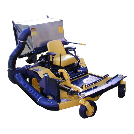
- Page 1 P P P GRASS COLLECTION PECO PECO PECO PECO PECO SYSTEM DESIGNED FOR: MODEL 39621223 - 28 GREAT DANE CHARIOT SERIES MOWER OPERATOR’S MANUAL ASSEMBLY OPERATION MAINTENANCE MANUAL PART#: Q0320 $4.00 REV: 0...
-
Page 2: Table Of Contents
PTO GRASS COLLECTION SYSTEM TABLE OF CONTENTS SECTION PAGE SECTION PAGE Safety - - - - - - - - - - - - - - - - - - - - - - - - - - - - - - - 2 2-13 Attachment Of The Boot To The Mower Deck - - 14 Safety Alert Symbols - - - - - - - - - - - - - - - - - - - - - - 3 2-14 Adjustment Of The Lengths Of The Hoses - - - - 14... -
Page 3: Safety Alert Symbols
SAFETY WARNING! NEVER operate the unit unless the discharge guard and either the deflector assembly or the vacuum collector adapter are fastened securely in place. WARNING! Do not work around the mower deck boot or the blower area until you are certain that the mower blades and the blower impeller have stopped rotating. -
Page 4: Warranty
PECO elects, without charge if the defect appears within 90 days from the date of installation of such part or before the expiration of the original warranty period, whichever is later. -
Page 5: Introduction And Description
1-1 Introduction Section II INSTALLATION FOR USE We are pleased to have you as a PECO customer. Your collection system has been designed to give you a low 2-1 Preparation Of Mower maintenance, simple, and effective way to collect the grass clippings from your mower. -
Page 6: Attaching Lower Frame Legs
Heat Guard Installation Figure 4. Left Lower Frame Leg Assembly Note: Heat Guard only to be used with Kohler engines. To install, place heat guard onto the top of the rear bumper of the mower. Fasten the heat guard by using (2) inlet clamps P#(B1668) underneath the heat guard and (2) ½”... -
Page 7: Attaching The Top Main Frame Assembly
Figure 8a. Top Main Frame without Air Cleaner Figure 6a. Removal of Blower Belt Guard Remove both screws to remove the Blower Belt Guard Figure 6b. Removal of Blower Pivot Pin Attach (2) 3/8”-16 x 1” HHCS (2) 3/8”-16 Flange Nuts To upper mounting holes Figure 8b. - Page 8 Figure 9. Figure 12. Aluminum Grass Container Assy. Lift Handle Assy. Handle Grip Handle Mount Bracket Latch Rod Figure 10. Aluminum Grass Container With Handle Attached Figure 11. Latch Hook Mechanism Assembled...
-
Page 9: Attaching The Aluminum Grass Container To
the handle mount bracket. With the handle in place, linkage rods to the main frame by using (1) rue-ring fasten the ball joint P#(K1442) to the end of the latch rod cotter pin P#(K1437) per side. To test the functionality of P#(A0260). - Page 10 Exploded Parts View...
- Page 11 Parts View 49/50 53/54/55 Item Part No. Qty. Description Item Part No. Qty. Description 1 - - - - E6004- - - - - - 1 - - - - Blower Cone 7” 34 - - - K0326- - - - - - 1 - - - - Belt Tension Rod 3/8”-16 (52”...
-
Page 12: Adjusting The Dump Mechanism
2-8 Adjusting The Dump Mechanism Gear Box Assy. The linkage rods may be adjusted in two places, at the Figure 15. adjusting screw P#(K1435 and the latch assembly items. See Figures 9 & 11 for visual clarification. To change the door closure tightness, screw the adjusting screw in or out. -
Page 13: Blower Cone Installation
2-11 Blower Cone Installation 2-12 Impeller Blade Removal/Replacement Thread (1) 5/16”-18 jam nut P#(K0120) onto each end of (2) 5/16”-18 x 2-1/2” HHCS P#(K0125). Now partially To Remove: First remove the center bolt (#1), washer thread the bolts into each of the two tabs located on the (#2) and spacer (#3) from the taper-lock bushing (#5). -
Page 14: Attachment Of The Boot To The Mower Deck
Figure 20. Hose Assembly Figure 19. Inlet Mower Deck Deflector Shield Upper Hose 5”- 6” Hose Clamp Deflector Shield Lower Hose 8” x 38” Hose Boot Boot 7”- 8” Hose Clamp Boot Plate 2-15 Attachment Of The Upper Hose 2-13 Attachment Of The Boot To The Slide a 5”-6”... -
Page 15: Front Weight Assembly
2-18 Front Weight Assembly Place (1) weight bracket P#(B0026) over each front caster. Fasten each weight bracket to the front caster loosely, by using (1) 3/8”-16 x 3-1/2” u-bolt P#(K0286) and (2) 3/8”-16 flange nuts P#(K1215) per bracket. When installing the 100 lb.weight you should have another person help position the weight onto a floor jack. -
Page 16: Operating Instructions
A. To disengage the blower, rotate the engagement been torn or worn through, replace with genuine handle towards the mower. PECO parts. WARNING: The blower will continue to spin. DO NOT After Each Use: TOUCH the blower, pulleys, or the belt until the tractor is turned off. -
Page 17: Lubrication
3. Check belt for proper tension. 5-1 Parts And Service Information 4-2 Lubrication PECO collection system owners should record the name and telephone number of their Service Center. Your Service Center will be happy to supply replacement NOTE: Use only white lithium based grease for parts, accessories, and do any service or repairs to your lubrication of the shaft on the blower assembly. -
Page 18: Safety Decals
SAFETY DECALS To promote safe operation, PECO supplies safety decals on all products manufactured. Damage can occur to safety decals either through shipment, use or reconditioning. Contact your local Service Center for replacement decals. Part #: R1050 Part #: R1049... -
Page 20: Notes
NOTES... - Page 21 P P P PECO PECO PECO PECO PECO P.O. BOX 1197 ARDEN, NORTH CAROLINA 28704 (800) 438-5823 OR (828) 684-1234 FAX: (828) 684-0858 EMAIL: pecoinc1@bellsouth.net WEBSITE: www.lawnvac.com...
Need help?
Do you have a question about the 39621223-28 and is the answer not in the manual?
Questions and answers