Table of Contents
Advertisement
Quick Links
Advertisement
Table of Contents

Related Manuals for Peco Country Clipper XLT Series


Summary of Contents for Peco Country Clipper XLT Series
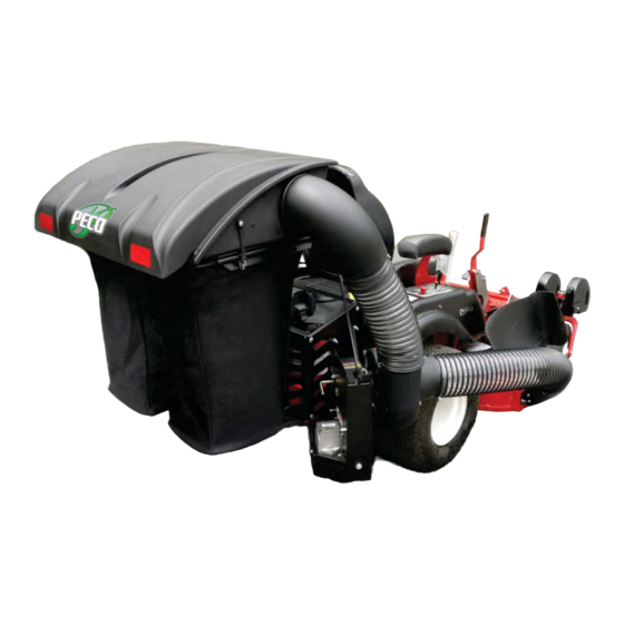
- Page 1 P P P P P P RESIDENTIAL PTO - GRASS PECO PECO PECO PECO PECO COLLECTION SYSTEM XLT Series 48” & 52” DECKS MODEL YEAR: 2018-NEWER Model# A2244 (629JP-001A) Reference#: 49120908 (629JH-001A) OPERATOR’S MANUAL ASSEMBLY OPERATION MAINTENANCE MANUAL PART#: Q0521...
-
Page 2: Table Of Contents
GRASS COLLECTION SYSTEM TABLE OF CONTENTS SECTION PAGE SECTION PAGE Safety - - - - - - - - - - - - - - - - - - - - - - - - - - - - - - 2 Length of Hose Adjustment - - - - - - - - - - - - - - - - - 19 Safety Alert Symbols - - - - - - - - - - - - - - - - - - - - - - 3 Upper Hose Installation - - - - - - - - - - - - - - - - - - - - 19... -
Page 3: Safety Alert Symbols
SAFETY WARNING! NEVER operate the mower unless the discharge guard and either the deflector assembly or the vacuum collector adapter are fastened securely in place. WARNING! Do not work around the mower deck boot or the blower area until you are certain that the mower blades and the blower impeller have stopped rotating. -
Page 4: Warranty
6. REMEDIED EXCLUSIVE: The only remedies the purchaser has in connection with the breach or performance of any warranty on New PECO, Inc. consumer products are set forth above. In no event will New PECO, Inc. be liable for special incidental or consequential damages. -
Page 5: Introduction And Description
Section I - INTRODUCTION AND DESCRIPTION Introduction Description We are pleased to have you as a PECO customer. Your The grass collection system is designed for turf collection system has been designed to give you a low maintenance where there is a need to collect the grass maintenance, simple, and effective way to collect the clippings as the mower cuts the turf. -
Page 6: Preparation Of Mower
Section II - INSTALLATION FOR USE The engine pulley assembly must be installed using an Preparation Of Mower arbor press or equivalent. During installation, opposite bearing inner race must be supported or bearing NOTE: The mower deck PTO belt must be removed damage may occur. -
Page 7: Rear Frame Assy & Installation
Rear Frame Assembly & Installation PREV MODEL To install the Rear Frame Mount Kit, first remove the (2) existing bolts located on the left and right side of the rear bumper. Position the Rear Frame Bracket (Item#1) up against the rear bumper and secure the Rear Frame Bracket by fastening (2) 3/8”-16 x 3-1/2”... - Page 8 Rear Frame Assembly & Installation (Cont.) 2022 MODEL To install the Rear Frame Mount Kit, first remove the (2) existing bolts located on the left and right side securing the Rear Bumper and completely remove the Rear Bumper, refer to Figure B below. Note: Some parts and part features have been hidden from view for visual clarity.
- Page 9 Rear Frame Assembly & Installation (Cont.) 2022 MODEL Then, install the Right Frame Bracket (Item #2) by first placing and aligning (1) 3/8” Washer (Item #7) between the Right Frame Bracket and Lower Frame and secure the Right Frame Bracket to the Lower Frame by using (1) 3/8”-16 x 3”...
-
Page 10: Pto Mount Assy Installation
PTO Mount Assembly Installation To Install the Right PTO Mount Plate (Item #1), first align the mounting holes to the holes on the Right Frame Bracket as shown in Figure A. Secure the Right PTO Mount Plate by using (2) 3/8”-16 x 1” Carriage Bolts (Item #3) and (2) 3/8”-16 Ny-Flange Lock Nuts (Item #4). -
Page 11: Lower Mount Tube Installation
Lower Mount Tube Installation Secure (2) Lower Mount Tubes ( Item #1) to the Rear Frame Bracket using (2) 5/16”-18 x 2” x 2-1/2” U-Bolts ( Item and (2) 5/16”-18 Ny-Flange Lock Nuts ( Item #3) PER TUBE. Allow the Lower Mount Tubes to rest on the tabs of the Rear Frame Bracket. -
Page 12: Belt Installation & Adjustment
Belt Installation and Adjustment Figure D Remove (3) 1/4”-20 x 1/2” HHSTS P#(K0353) from the Loosen The gearbox pulley guard located on the bottom of the PTO Adjustment Bolt assembly (Refer to Figure A). Figure A Slide Gear Box Towards The Engine Pulley Connect the belt A56K P#(M0239) from the engine pulley to the lower gear box pulley (Figure E). -
Page 13: Top Assy To Upper Frame Assy Installation
Top Assembly To Upper Frame Assembly Installation Align the Top Assembly Pivot Holes to the Upper Frame Assembly. See Figure A below. Before fastening, pull Rubber Dust Guard outward to seal against Upper Frame Assembly (towards the mower’s operator seat). Fasten the Top Assembly to the Upper Frame Assembly using (2) 5/16”-18 x 2-1/2”... -
Page 14: Hinge Kit Assy Installation
Hinge Kit Assembly Installation Assemble the Hinge Kit using (1) Latch Plate P#(B0884), (1) 5/16”-18 x 1-1/4” HHCS P#(K1156), (1) 5/16”-18 Ny- Flange Lock Nut P#(K2516), (3) 5/16” Flat Washers P#(K0042), (1) Latch Spacer P#(S0006), (2) Extra Heavy 5/16” Fender Washers P#(K0505) and (1) 5/16”-18 Lock Nut P#(K0506). Leave the nuts loose enough to allow fluid movement of the top when opening and closing. -
Page 15: Bag Assembly
Bag Assembly First, take one of the Bag Ring Split Ends and insert it through the Bag Seam Opening. Next, rotate the Bag around the Bag Ring (1) full turn (360 degrees) until the Bag Ring Split Ends and the Bag Seam Opening are positioned on the same side. -
Page 16: Blower Cone Installation
Blower Cone Installation Align the bolt holes of the Blower Cone (Item #1) to the bolt holes located on the Blower Housing of the PTO Assembly. Secure the Blower Cone to the Blower Housing by using (3) 1/4”-20 x 3/4” HHCS (Item #4), (3) 1/4” Lock Washers (Item #3), and (3) 1/4”... -
Page 17: Boot Kit Installation
Boot Kit Installation For 2018-2019 Models : Attach Rubber Strap P#(J4009) to mower deck using (1) P#(K1025) 1/4”-20 Carriage Bolt, (1) P#(K0037) 1/4” Flat Washer and (1) P#(K2014) 1/4”-20 Ny-Flange Lock Nut. Open end of hook should be facing deck discharge. Refer to Figure A Figure A Rubber Strap... - Page 18 Boot Kit Installation (Continued) For 2020 - Newer Models : Secure the Boot Plate (Item #1) to the Aluminum Boot P#(E0032A) using (2) 3/8”-16 x 1” Carriage Bolts (Item #2) and (2) 3/8”-16 Nylon Flange Locknuts (Item #3). Insert the Carriage Bolts from the inside of the Boot so the threads are on the top of the Boot.
-
Page 19: Length Of Hose Adjustment
Length Of Hose Adjustment Lower Hose To Blower Cone Installation The hoses in the following steps must be cut to fit your machine. Do not cut the hoses until you have tried to fit Slide a Hose Clamp over both ends of the Lower Hose. them on your machine. -
Page 20: Impeller Blade Removal/Replacement
Impeller Blade Removal/Replacement To Remove: To access the impeller blade, remove the Blower Cone and Blower Cone Hardware from the Blower Housing (Item #1). Remove the 5/16”-24 x 1-1/4” LH HHCS (Item #3) and (1) Washer (Item #4) (Refer to Figure A). Insert (1) 1/2”-13 x 1”... -
Page 21: Weight Kit Installation
Weight Kit Installation Position the Dual Weight Bracket Base (Item #2) under the caster tubing w/ opening towards caster fork. Next, position the Weight Bracket Clamp (Item #3) on top of caster tubing w/ opening towards caster fork. Align the (4) holes of the Weight Bracket Clamp (Item #3) to the holes in the Dual Weight Bracket Base (Item #2). Loosely fasten the Weight Bracket Clamp (Item #3) to the Weight Bracket Base (Item#1) using (4) 5/16"-18 x 3"... -
Page 22: Exploded Views & Parts List
A2194_01 PTO-R BASE ASSEMBLY EXPLODED PARTS VIEW... - Page 23 A2194_01 PTO-R BASE ASSEMBLY PARTS LIST...
- Page 24 A2266 PTO Drive Assembly / 3 Blade Impeller...
- Page 25 A2101 Top Assembly / Standard Exploded Parts View...
- Page 26 A2222 Top Assembly / Base Exploded Parts View...
-
Page 30: Safety Decals
SAFETY DECALS To promote safe operation, New PECO, Inc. supplies safety decals on all products manufactured. Damage can occur to safety decals either through shipment, use or reconditioning. Contact your local Service Center for replacement decals. P P P PECO... -
Page 31: Operating Instructions
SECTION III OPERATING INSTRUCTIONS General Safety Disengagement Of The PTO Assembly Only qualified people familiar with this operator’s manual A. To disengage the PTO assembly, move Bagger PTO and the mower’s operator’s manual should operate this switch to the off position. machine. -
Page 32: Lubrication
If for any reason your Service Center is unable to service your collection system or supply replacement parts, contact New PECO, Inc. and include the following information on the chart below. DOCUMENT THE FOLLOWING INFORMATION FOR FUTURE REFERENCE... -
Page 34: Troubleshooting
Troubleshooting 2017 (v1.0) Collection System Performance Problem Possible Cause Corrective Action — Cutting blades are bent or — Install new cutting blade unbalanced — Loose blower pulley or pulley Abnormal Vibration — Tighten the pulley assembly — Contact dealer to replace —... - Page 35 Notes...
- Page 36 P P P P P P PECO PECO PECO PECO PECO New PECO, Inc. 10 Walden Dr | Arden, North Carolina 28704 Phone: 1-800-438-5823 | 828-684-1234 Fax: 828-684-0858 Email: peco@lawnvac.com Website: www.lawnvac.com...
Need help?
Do you have a question about the Country Clipper XLT Series and is the answer not in the manual?
Questions and answers