Table of Contents
Advertisement
Quick Links
Advertisement
Chapters
Table of Contents
Troubleshooting

Related Manuals for IEI Technology FLEX-BX100-ULT5


Summary of Contents for IEI Technology FLEX-BX100-ULT5
- Page 1 FLEX-BX100-ULT5 eFLEX-BX100-ULT5 Box PC MODEL: MODEL: FLEX-BX100-ULT5 AI Box PC with 8 Gen. Intel® Core™ i5-8365UE CPU, DDR4, HDMI, USB 3.2 Gen 2, Triple GbE, RS-232/422/485, M.2 M-key/A-key, PoE, RoHS Compliant User Manual Page i Rev. 1.00 – January 14, 2021...
- Page 2 FLEX-BX100-ULT5 Revision Date Version Changes January 14, 2021 1.00 Initial release Page ii...
- Page 3 FLEX-BX100-ULT5 Safety Instructions Warning! Read the user manual before connecting the system to the power source. Vorsicht! Bitte lesen Sie die Bedienungsanleitung, bevor Sie das System an eine Stromquelle anschließen. Attention! Avant de brancher le système à la source d'alimentation, consultez le mode d'emploi.
- Page 4 FLEX-BX100-ULT5 Warning! Ultimate disposal of this product should be handled according to all national laws and regulations. Vorsicht! Die Entsorgung dieses Produkts sollte gemäß allen Bestimmungen und Gesetzen des Landes erfolgen. Attention! La mise au rebut ou le recyclage de ce produit sont généralement soumis aux lois et/ou directives de respect de l'environnement.
- Page 5 FLEX-BX100-ULT5 Copyright COPYRIGHT NOTICE The information in this document is subject to change without prior notice in order to improve reliability, design and function and does not represent a commitment on the part of the manufacturer. In no event will the manufacturer be liable for direct, indirect, special, incidental, or consequential damages arising out of the use or inability to use the product or documentation, even if advised of the possibility of such damages.
- Page 6 FLEX-BX100-ULT5 Manual Conventions WARNING Warnings appear where overlooked details may cause damage to the equipment or result in personal injury. Warnings should be taken seriously. CAUTION Cautionary messages should be heeded to help reduce the chance of losing data or damaging the product.
-
Page 7: Table Of Contents
FLEX-BX100-ULT5 Table of Contents 1 INTRODUCTION ......................1 1.1 O ........................2 VERVIEW 1.2 M ....................2 ODEL ARIATIONS 1.3 F ........................3 EATURES 1.4 F ......................3 RONT ANEL 1.5 R ....................... 4 ANEL 1.6 T ......................... 4 ANEL 1.7 B... - Page 8 FLEX-BX100-ULT5 3.12.1 Installation Checklist ..................29 3.12.2 Power-on Procedure ..................29 3.13 R ....................30 ESET THE YSTEM 3.14 S ..................30 OFTWARE NSTALLATION 3.14.1 Driver Download ................... 31 4 BIOS ..........................33 4.1 I ......................34 NTRODUCTION 4.1.1 Starting Setup ....................34 4.1.2 Using Setup ......................
- Page 9 FLEX-BX100-ULT5 4.4.2.1 PCI Express Configuration ............... 61 4.4.2.2 SATA And RST Configuration ..............62 4.5 S ......................... 64 ECURITY 4.6 B ........................65 4.7 S & E ......................67 5 TROUBLESHOOTING AND MAINTENANCE ............. 68 5.1 S ................. 69 YSTEM...
- Page 10 FLEX-BX100-ULT5 6.3.6 USB 3.2 Gen 2 Connectors (USB_CON1, USB_CON2) ......... 84 6.4 J ........................84 UMPERS 6.4.1 Flash Descriptor Security Override Jumper ............ 84 A REGULATORY COMPLIANCE ................86 B SAFETY PRECAUTIONS ..................91 B.1 S ..................... 92 AFETY RECAUTIONS B.1.1 General Safety Precautions ................
- Page 11 FLEX-BX100-ULT5 List of Figures Figure 1-1: FLEX-BX100-ULT5 Series Box PC ................2 Figure 1-2: Front Panel ........................3 Figure 1-3: Rear Panel ........................4 Figure 1-4: Top Panel ........................4 Figure 1-5: Bottom Panel ....................... 5 Figure 1-6: Dimensions with Mounting Brackets (mm) .............. 8 Figure 3-1: HDD Cover Retention Screws ..................
- Page 12 FLEX-BX100-ULT5 Figure 6-1: Main Board Layout Diagram ..................73 Page xii...
- Page 13 FLEX-BX100-ULT5 List of Tables Table 1-1: Model Variations ......................2 Table 1-2: Technical Specifications ....................7 Table 2-1: Package List ........................ 11 Table 2-2: Optional Items ......................12 Table 3-1: RS-232/422/485 Serial Port (COM1) Pinouts ............26 Table 3-2: COM1 Pin 9 Setting Jumper Settings (JP5) ............. 27 Table 4-1: BIOS Navigation Keys ....................
- Page 14 FLEX-BX100-ULT5 List of BIOS Menus BIOS Menu 1: Main ........................36 BIOS Menu 2: Advanced ......................37 BIOS Menu 3: CPU Configuration ....................38 BIOS Menu 4: PCH-FW Configuration ..................40 BIOS Menu 5: PTT Configuration ....................41 BIOS Menu 6: Trusted Computing ....................42 BIOS Menu 7: ACPI Settings .......................
-
Page 15: Introduction
FLEX-BX100-ULT5 Chapter Introduction Page 1... -
Page 16: Overview
FLEX-BX100-ULT5 1.1 Overview Figure 1-1: FLEX-BX100-ULT5 Series Box PC The FLEX-BX100-ULT5 box PC is powered by 8th Generation Intel® Core™ i5-8365UE / ® Celeron 4305UE Processor which is a System-on-Chip (SoC) that ensures optimal memory, graphics, and peripheral I/O support. The system comes with 4.0 GB of DDR4 SO-DIMM memory ensuring smooth data throughputs with reduced bottlenecks and fast system access. -
Page 17: Features
FLEX-BX100-ULT5 1.3 Features The FLEX-BX100-ULT5 has the following features ® ® generation Intel Core™ i5-8365UE / Celeron 4305UE processor Preinstalled with 4 GB of DDR4 memory (system max. 32 GB) Three PCIe GbE RJ-45 connectors (two with PoE support) ... -
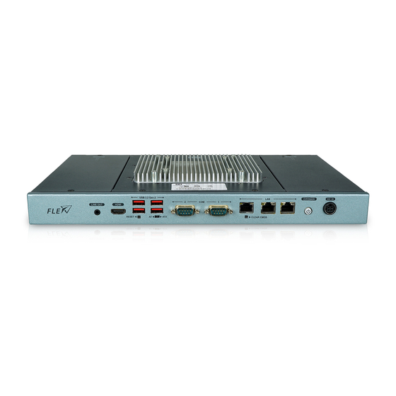
Page 18: Rear Panel
FLEX-BX100-ULT5 1.5 Rear Panel The rear panel of the FLEX-BX100-ULT5 has two knockout holes for the installation of the optional Wi-Fi antenna (Figure 1-3). Figure 1-3: Rear Panel 1.6 Top Panel The top panel has retention screw holes that support VESA mounting. The top panel also provides access to the internal HDD/SSD bay and the PoE card slots. -
Page 19: Bottom Panel
FLEX-BX100-ULT5 1.7 Bottom Panel The bottom surface of the FLEX-BX100-ULT5 contains four retention screw holes for installing two side mounting brackets. Figure 1-5: Bottom Panel Page 5... -
Page 20: Technical Specifications
FLEX-BX100-ULT5 1.8 Technical Specifications The specifications for the FLEX-BX100-ULT5 box PCs are listed below. FLEX-BX100-ULT5 8th Generation Intel® Core™ i5-8365UE CPU (6M cache, up to 4.2 GHz) 8th Generation Intel® Celeron® 4305UE CPU (2M cache, 2.0 GHz) BIOS AMI UEFI BIOS... -
Page 21: Table 1-2: Technical Specifications
FLEX-BX100-ULT5 1 x Power button with LED indicator 1 x Reset button Buttons and Indicators 1 x AT/ATX mode switch 1 x Clear CMOS button 12 V DC PoE IEEE802.3af/at/bt (optional, redundancy, power load-sharing) Power Requirement Support AT/ATX mode Chassis Construction... -
Page 22: Dimensions
FLEX-BX100-ULT5 1.9 Dimensions The dimensions of the FLEX-BX100-ULT5 are listed below and shown in Figure 1-6. Figure 1-6: Dimensions with Mounting Brackets (mm) Page 8... -
Page 23: Unpacking
FLEX-BX100-ULT5 Chapter Unpacking Page 9... -
Page 24: Unpacking
Contact the IEI reseller or vendor the FLEX-BX100-ULT5 was purchased from or contact an IEI sales representative directly by sending an email to sales@ieiworld.com. The FLEX-BX100-ULT5 box PC is shipped with the following components: Quantity Item... -
Page 25: Table 2-1: Package List
FLEX-BX100-ULT5 96 W power adapter Wall mount bracket Screws (M4*8) for VESA mounting Screws (M4*6) for mounting brackets Screws (M3*4) for HDD installation Backup screws (M4*4) for top panel installation Foot pad Table 2-1: Package List Page 11... -
Page 26: Optional Items
FLEX-BX100-ULT5 2.3 Optional Items The following are optional component(s) which may be separately purchased: IEEE802.3af/at PoE PD module (P/N: GPOE-PD-AT01-R10) IEEE802.3af/at/bt PoE PD module (P/N: GPOE-PD-BT01-R10) Wi-Fi kit (2T2R, 802.11ac/a/b/g/n and BT V4.1, NGFF 2230 Type A-E) (P/N: EMB-WIFI-KIT02E-R10) Table 2-2: Optional Items... -
Page 27: Installation
FLEX-BX100-ULT5 Chapter Installation Page 13... -
Page 28: Anti-Static Precautions
During the time the board is handled, frequently touch any conducting materials that are connected to the ground. Use an anti-static pad: When configuring the FLEX-BX100-ULT5, place it on an anti-static pad. This reduces the possibility of ESD damaging the FLEX-BX100-ULT5. -
Page 29: Installation Procedure
FLEX-BX100-ULT5. 3.3 Installation Procedure To properly install the FLEX-BX100-ULT5, the following steps must be followed. Detailed descriptions of these instructions are listed in the sections that follow. Step 1:... -
Page 30: Hdd Installation
FLEX-BX100-ULT5 3.4 HDD Installation To install the HDD into the system, please follow the steps below: Step 1: Remove the HDD cover retention screws located on the left side of the top panel. Slide the cover upwards to remove it. -
Page 31: Figure 3-3: Hdd Retention Screws
Connect the SATA cable to the rear of HDD from the motherboard. Step 5: Install the HDD into the FLEX-BX100-ULT5 by aligning the retention screw holes in the HDD brackets with the retention screw holes on the chassis. Insert the four retention screws. -
Page 32: Poe Pd Module Installation (Optional)
FLEX-BX100-ULT5 3.5 PoE PD Module Installation (Optional) An IEI PoE module must be installed before start using the FLEX-BX100-ULT5 as a PoE powered device (PD). To install the optional PoE module, follow the steps below. Step 1: Remove the PoE card cover retention screws located on the right side of the top panel. -
Page 33: Ssd Installation (Optional)
FLEX-BX100-ULT5 Step 4: Line up the notch on the PoE module with the notch on the connector. Slide the PoE module into the socket at an angle of about 20º. Step 5: Push the other end of the PoE module down and secure the module with the retention screw previously removed. -
Page 34: Figure 3-8: M.2 Slot Location
FLEX-BX100-ULT5 Figure 3-8: M.2 Slot Location Step 3: Remove the on-board retention screw as shown in Figure 3-9. Figure 3-9: Removing the M.2 Module Retention Screw Step 4: Line up the notch on the module with the notch on the slot. Slide the M.2 module into the socket at an angle of about 20º... -
Page 35: Figure 3-10: Inserting The M.2 Module Into The Slot At An Angle
FLEX-BX100-ULT5 Figure 3-10: Inserting the M.2 Module into the Slot at an Angle Step 5: Push the M.2 module down and secure it with the previously removed retention screw (Figure 3-11). Figure 3-11: Securing the M.2 Module Step 6: Re-install the rear covers and secure them with the eight retention screws previously removed.Step 0:... -
Page 36: Wireless Lan Module Installation (Optional)
Thus, more strength is required when lifting the center cover. Step 2: Remove the two knockouts for antenna installation. The two knockouts are located on the rear panel of the FLEX-BX100-ULT5 (Figure 3-12). Figure 3-12: Knockouts on Rear Panel for Wireless Antennas Step 3: Locate the M.2 A-key slot (Figure 3-13). -
Page 37: Figure 3-14: Inserting The Wlan Module
FLEX-BX100-ULT5 Step 5: Line up the notch on the WLAN module with the notch on the slot. Slide the WLAN module into the slot at an angle of about 20º (Figure 3-14). Figure 3-14: Inserting the WLAN Module Step 6: Secure the WLAN module with the screw previously removed (Figure 3-16). -
Page 38: Figure 3-16: Connecting Rf Cables
FLEX-BX100-ULT5 Step 7: Connect the two RF cables to the antenna connectors on the WLAN module (Figure 3-16). Figure 3-16: Connecting RF Cables Step 8: Remove the nut and washer from the SMA connector at the other end of the RF cable. -
Page 39: Mounting The System
FLEX-BX100-ULT5 3.8 Mounting the System To mount only the box PC onto a wall or some other surface using the two mounting brackets, please follow the steps below. Step 1: Turn the box PC over. Step 2: Align the two retention screw holes in each bracket with the retention screw holes on the sides of the bottom surface. -
Page 40: Rs-232/422/485 Serial Port (Com1) Selection
Insert retention screws into each bracket to secure the system to the wall. Step 0: 3.9 RS-232/422/485 Serial Port (COM1) Selection The front panel of the FLEX-BX100-ULT5 has one D-sub 9 male connectors for RS-232/422/485 connection. The serial communication mode selection can be made through the BIOS options (see Section 4.3.7.1.1). -
Page 41: Com1 Pin 9 Selection
FLEX-BX100-ULT5 3.9.2 COM1 Pin 9 Selection Pin 9 on the COM1 DB-9 connector can be set as the ring (RI) signal, +5 V or +12 V. The jumper selection options are shown in Table 3-2. Description Short 1-2 COM1 RI Pin use +12 V... -
Page 42: Clear Cmos
Figure 3-21: Clear CMOS Button Location 3.11 AT/ATX Mode Selection AT or ATX power mode can be used on the FLEX-BX100-ULT5. The selection is made through an AT/ATX switch located on the front panel (Figure 3-22). Figure 3-22: AT/ATX Switch Location... -
Page 43: Power-On Procedure
The system is securely mounted 3.12.2 Power-on Procedure To power-on the FLEX-BX100-ULT5 please follow the steps below: Step 1: Connect the power source to the power inlet on the front panel. Ensure to connect the power cord to a socket-outlet with earthing connection. -
Page 44: Reset The System
Figure 3-24. Press the reset button to reboot the system. Figure 3-24: Reset Button Location 3.14 Software Installation All the drivers for the FLEX-BX100-ULT5 are available on IEI Resource Download Center (https://download.ieiworld.com). Type FLEX-BX100-ULT5 and press Enter to find all the relevant software, utilities, and documentation. -
Page 45: Driver Download
3.14.1 Driver Download To download drivers from IEI Resource Download Center, follow the steps below. Step 1: Go to https://download.ieiworld.com. Type FLEX-BX100-ULT5 and press Enter. Step 2: All product-related software, utilities, and documentation will be listed. You can choose Driver to filter the result. - Page 46 FLEX-BX100-ULT5 NOTE: To install software from the downloaded ISO image file in Windows 8, 8.1 or 10, double-click the ISO file to mount it as a virtual drive to view its content. Page 32...
-
Page 47: Bios
FLEX-BX100-ULT5 Chapter BIOS Page 33... -
Page 48: Introduction
FLEX-BX100-ULT5 4.1 Introduction The BIOS is programmed onto the BIOS chip. The BIOS setup program allows changes to certain system settings. This chapter outlines the options that can be changed. NOTE: Some of the BIOS options may vary throughout the life cycle of the product and are subject to change without prior notice. -
Page 49: Getting Help
FLEX-BX100-ULT5 Function Decrease the numeric value or make changes Page up Move to the next page Page down Move to the previous page Main Menu – Quit and do not save changes into CMOS Status Page Setup Menu and Option Page Setup Menu --... -
Page 50: Main
FLEX-BX100-ULT5 4.2 Main The Main BIOS menu (BIOS Menu 1) appears when the BIOS Setup program is entered. Aptio Setup Utility – Copyright (C) 2020 American Megatrends, Inc. Main Advanced Chipset Security Boot Save & Exit BIOS Information BIOS Vendor American Megatrends Set the Date. -
Page 51: Advanced
FLEX-BX100-ULT5 System Date [xx/xx/xx] Use the System Date option to set the system date. Manually enter the day, month and year. System Time [xx:xx:xx] Use the System Time option to set the system time. Manually enter the hours, minutes and seconds. -
Page 52: Cpu Configuration
FLEX-BX100-ULT5 4.3.1 CPU Configuration Use the CPU Configuration menu (BIOS Menu 3) to view detailed CPU specifications and configure the CPU. Aptio Setup Utility – Copyright (C) 2020 American Megatrends, Inc. Advanced CPU Configuration When enabled, a VMM can utilize the additional... -
Page 53: Active Processor Cores [All]
FLEX-BX100-ULT5 Active Processor Cores [All] Use the Active Processor Cores BIOS option to enable numbers of cores in the processor package. Enable all cores in the processor package. EFAULT Enable one core in the processor package. ... -
Page 54: Pch-Fw Configuration
FLEX-BX100-ULT5 4.3.2 PCH-FW Configuration The PCH-FW Configuration menu (BIOS Menu 4) allows Intel® Active Management Technology (AMT) options to be configured. Aptio Setup Utility – Copyright (C) 2020 American Megatrends, Inc. Advanced AMT BIOS Features [Enabled] When disabled AMT BIOS... -
Page 55: Ptt Configuration
FLEX-BX100-ULT5 4.3.2.1 PTT Configuration Use the PTT Configuration menu (BIOS Menu 6) to configure settings related to the Trusted Platform Module (TPM). Aptio Setup Utility – Copyright (C) 2020 American Megatrends, Inc. Advanced PTT Capability / State 1 / 0 Select TPM device: PTT or dTPM. -
Page 56: Trusted Computing
FLEX-BX100-ULT5 4.3.3 Trusted Computing Use the Trusted Computing menu (BIOS Menu 6) to configure settings related to the Trusted Computing Group (TCG) Trusted Platform Module (TPM). Aptio Setup Utility – Copyright (C) 2020 American Megatrends, Inc. Advanced Configuration Enables or Disables TPM... -
Page 57: Acpi Settings
FLEX-BX100-ULT5 4.3.4 ACPI Settings The ACPI Settings menu (BIOS Menu 7) configures the Advanced Configuration and Power Interface (ACPI) options. Aptio Setup Utility – Copyright (C) 2020 American Megatrends, Inc. Advanced ACPI Settings Select the highest ACPI sleep state the system... -
Page 58: Rtc Wake Settings
FLEX-BX100-ULT5 4.3.5 RTC Wake Settings The RTC Wake Settings menu (BIOS Menu 8) configures RTC wake event. Aptio Setup Utility – Copyright (C) 2020 American Megatrends, Inc. Advanced Wake system with Fixed Time [Disabled] Enable or disable System wake on alarm event. When... -
Page 59: Iwdd H/W Monitor
FLEX-BX100-ULT5 Wake up second After setting the alarm, the computer turns itself on from a suspend state when the alarm goes off. 4.3.6 iWDD H/W Monitor The iWDD H/W Monitor menu (BIOS Menu 9) contains the fan configuration submenus and displays operating temperature, fan speeds and system voltages. -
Page 60: F81866 Super Io Configuration
FLEX-BX100-ULT5 +V3.3A +V1.05A +VCCSA 4.3.7 F81866 Super IO Configuration Use the F81866 Super IO Configuration menu (BIOS Menu 10) to set or change the configurations for the serial ports. Aptio Setup Utility – Copyright (C) 2020 American Megatrends, Inc. Advanced... -
Page 61: Serial Port N Configuration
FLEX-BX100-ULT5 4.3.7.1 Serial Port n Configuration Use the Serial Port n Configuration menu (BIOS Menu 11) to configure the serial port n. Aptio Setup Utility – Copyright (C) 2020 American Megatrends, Inc. Advanced Serial Port 1 Configuration Enable or Disable Serial... -
Page 62: Serial Port Console Redirection
FLEX-BX100-ULT5 4.3.7.1.2 Serial Port 2 Configuration Serial Port [Enabled] Use the Serial Port option to enable or disable the serial port. Disabled Disable the serial port Enable the serial port Enabled EFAULT 4.3.8 Serial Port Console Redirection The Serial Port Console Redirection menu (BIOS Menu 12) allows the console redirection options to be configured. -
Page 63: Legacy Console Redirection Settings
FLEX-BX100-ULT5 Console Redirection [Disabled] Use Console Redirection option to enable or disable the console redirection function. Disabled the console redirection function Disabled EFAULT Enabled the console redirection function Enabled 4.3.8.1 Legacy Console Redirection Settings The Legacy Console Redirection Settings menu (BIOS Menu 13) allows the legacy console redirection options to be configured. -
Page 64: Console Redirection Settings
FLEX-BX100-ULT5 4.3.8.2 Console Redirection Settings The Console Redirection Settings menu (BIOS Menu 14) allows the console redirection options to be configured. The option is active when Console Redirection option is enabled. Aptio Setup Utility – Copyright (C) 2020 American Megatrends, Inc. -
Page 65: Bits Per Second [115200]
FLEX-BX100-ULT5 Bits per second [115200] Use the Bits per second option to specify the serial port transmission speed. The speed must match the other side. Long or noisy lines may require lower speeds. 9600 Sets the serial port transmission speed at 9600. -
Page 66: Usb Configuration
FLEX-BX100-ULT5 Stop Bits [1] Use the Stop Bits option to specify the number of stop bits used to indicate the end of a serial data packet. Communication with slow devices may require more than 1 stop bit. Sets the number of stop bits at 1. -
Page 67: Csm Configuration
FLEX-BX100-ULT5 Legacy USB Support [Enabled] Use the Legacy USB Support BIOS option to enable USB mouse and USB keyboard support. Normally if this option is not enabled, any attached USB mouse or USB keyboard does not become available until a USB compatible operating system is fully booted with all USB drivers loaded. -
Page 68: Nvme Configuration
FLEX-BX100-ULT5 CSM Support [Enabled] Use the CSM Support BIOS option to enable or disable CSM support. CSM support disabled Disabled CSM support enabled Enabled EFAULT 4.3.11 NVMe Configuration Use the NVMe Configuration (BIOS Menu 17) menu to display the NVMe controller and device information. -
Page 69: Iei Feature
FLEX-BX100-ULT5 4.3.12 IEI Feature Use the IEI Feature menu (BIOS Menu 18) to configure One Key Recovery function. Aptio Setup Utility – Copyright (C) 2020 American Megatrends, Inc. Advanced iEi Feature Auto Recovery Function Reboot and recover Auto Recovery Function... -
Page 70: Chipset
FLEX-BX100-ULT5 4.4 Chipset Use the Chipset menu (BIOS Menu 19) to configure the system chipset. Aptio Setup Utility – Copyright (C) 2020 American Megatrends, Inc. Main Advanced Chipset Security Boot Save & Exit > System Agent (SA) Configuration System Agent (SA) >... -
Page 71: Memory Configuration
FLEX-BX100-ULT5 VT-d [Disabled] Use the VT-d option to enable or disable VT-d support. Disable VT-d support. Disabled EFAULT Enable VT-d support. Enabled 4.4.1.1 Memory Configuration Use the Memory Configuration submenu (BIOS Menu 21) to display the memory information. -
Page 72: Graphics Configuration
FLEX-BX100-ULT5 4.4.1.2 Graphics Configuration Use the Graphics Configuration menu (BIOS Menu 22) to configure the graphics settings. Aptio Setup Utility – Copyright (C) 2020 American Megatrends, Inc. Chipset Graphics Configuration Select DVMT 5.0 Pre-Allocated (Fixed) DVMT Pre-Allocated [32M] Graphics Memory size used... -
Page 73: Pch-Io Configuration
FLEX-BX100-ULT5 EFAULT Primary IGFX Boot Display [VBIOS Default] Use the Primary IGFX Boot Display option to select the display device used by the system when it boots. VBIOS Default EFAULT HDMI LVDS Backlight Control [LED] Use the Backlight Control option to specify the backlight control mode. -
Page 74: Restore Ac Power Loss [Last State]
FLEX-BX100-ULT5 Restore AC Power Loss [Last State] Use the Restore AC Power BIOS option to specify what state the system returns to if there is a sudden loss of power to the system. Power Off The system remains turned off ... -
Page 75: Pci Express Configuration
FLEX-BX100-ULT5 4.4.2.1 PCI Express Configuration Use the PCI Express Configuration submenu (BIOS Menu 24) to configure the PCI Express slots. Aptio Setup Utility – Copyright (C) 2020 American Megatrends, Inc. Chipset PCI Express Configuration PCI Express Root Port Settings. > M2_A1 >... -
Page 76: Sata And Rst Configuration
FLEX-BX100-ULT5 Detect Non-Compliance Device [Disabled] Use the Detect Non-Compliance Device option to enable or disable detecting if a non-compliance PCI Express device is connected to the PCI Express slot. Disabled Disables to detect if a non-compliance PCI EFAULT Express device is connected to the PCI Express slot. -
Page 77: Sata Mode Selection [Ahci]
FLEX-BX100-ULT5 SATA Mode Selection [AHCI] Use the SATA Mode Selection option to configure how the SATA controller(s) operate. Configures SATA devices as AHCI device. AHCI EFAULT Intel RST Configures SATA devices as RAID device. Premium with Intel... -
Page 78: Security
FLEX-BX100-ULT5 4.5 Security Use the Security menu (BIOS Menu 26) to set system and user passwords. Aptio Setup Utility – Copyright (C) 2020 American Megatrends, Inc. Main Advanced Chipset Security Boot Save & Exit Password Description Set Administrator Password If ONLY the Administrator’s password is set,... -
Page 79: Boot
FLEX-BX100-ULT5 4.6 Boot Use the Boot menu (BIOS Menu 27) to configure system boot options. Aptio Setup Utility – Copyright (C) 2020 American Megatrends, Inc. Main Advanced Chipset Security Boot Save & Exit Boot Configuration Select the keyboard Bootup NumLock State... -
Page 80: Quiet Boot [Enabled]
FLEX-BX100-ULT5 Quiet Boot [Enabled] Use the Quiet Boot BIOS option to select the screen display when the system boots. Normal POST messages displayed Disabled OEM Logo displayed instead of POST messages Enabled EFAULT Launch PXE OpROM [Disabled] Use the Launch PXE OpROM option to enable or disable boot option for legacy network devices. -
Page 81: Save & Exit
FLEX-BX100-ULT5 4.7 Save & Exit Use the Save & Exit menu (BIOS Menu 28) to load default BIOS values, optimal failsafe values and to save configuration changes. Aptio Setup Utility – Copyright (C) 2020 American Megatrends, Inc. Main Advanced Chipset... -
Page 82: Troubleshooting And Maintenance
FLEX-BX100-ULT5 Chapter Troubleshooting and Maintenance Page 68... -
Page 83: System Maintenance Overview
Failure to follow these instructions may lead to personal injury and system damage. To preserve the working integrity of the FLEX-BX100-ULT5 box PC, the system must be properly maintained. If box PC components need replacement, the proper maintenance procedures must be followed to ensure the system can continue to operate normally. -
Page 84: The System Doesn't Boot Up
If all troubleshooting measures have been taken and the system still fails to start, contact the IEI reseller or vendor you purchased the FLEX-BX100-ULT5 from or contact an IEI sales representative directly. To contact an IEI sales representative, please send an email to sales@ieiworld.com. -
Page 85: Component Replacement
WARNING! Users are not advised to attempt to repair or replace any internal or external components of the FLEX-BX100-ULT5 box PC. If any other components fail or need replacement, contact the IEI reseller or vendor you purchased the FLEX-BX100-ULT5 from or contact an IEI sales representative directly. -
Page 86: Interface Connectors
FLEX-BX100-ULT5 Chapter Interface Connectors Page 72... -
Page 87: Peripheral Interface Connectors
FLEX-BX100-ULT5 6.1 Peripheral Interface Connectors The FLEX-BX100-ULT5 box PC motherboard comes with a number of peripheral interface connectors and configuration jumpers. The connector locations are shown in Figure 6-1. The Pin 1 locations of the on-board connectors are also indicated in the diagram below. -
Page 88: Internal Peripheral Connectors
FLEX-BX100-ULT5 6.2 Internal Peripheral Connectors Internal peripheral connectors are found on the motherboard and are only accessible when the motherboard is outside of the chassis. The table below shows a list of the peripheral interface connectors on the motherboard. Pinouts of these connectors can be found in the following sections. -
Page 89: Digital I/O Connector (Dio1)
FLEX-BX100-ULT5 6.2.2 Digital I/O Connector (DIO1) PIN NO. DESCRIPTION PIN NO. DESCRIPTION DOUT3 DOUT2 DOUT1 DOUT0 DIN3 DIN2 DIN1 DIN0 Table 6-3: Digital I/O Connector (DIO1) Pinouts 6.2.3 Inverter Connector (INVERTER1) PIN NO. -
Page 90: A-Key Slot (M2_A1)
FLEX-BX100-ULT5 A6P_L A6M_L A5P_L A5M_L A4P_L A4M_L A3P_L A3M_L CLK1P_L CLK1M_L A2P_L A2M_L A1M_L A1P_L A0M_L A0P_L Table 6-5: LVDS Connector (LVDS1) Pinouts 6.2.5 M.2 A-Key Slot (M2_A1) PIN NO. DESCRIPTION PIN NO. DESCRIPTION +V3.3A USB+ +V3.3A USB- Module Key... -
Page 91: M-Key Slot (M2_M2)
FLEX-BX100-ULT5 PCIE_TX+ PCIE_TX- PCIE_RX+ PCIE_RX- CLK_PCIE+ CLK_PCIE- BUF_PLT_RST# BT_DISABLE PCIE_WAKE# WIFI_DISABLE SMB_DATA SMB_CLK +V3.3A +V3.3A Table 6-6: M.2 A-Key Slot (M2_A1) Pinouts 6.2.6 M.2 M-key Slot (M2_M2) PIN NO. DESCRIPTION PIN NO. DESCRIPTION +3.3VA +3.3VA PCIE_RX- PCIE_RX+ Page 77... - Page 92 FLEX-BX100-ULT5 +3.3VA PCIE_TX- +3.3VA PCIE_TX+ +3.3VA +3.3VA PCIE_RX- +3.3VA PCIE_RX+ PCIE_TX- PCIE_TX+ PCIE_RX- PCIE_RX+ PCIE_TX- PCIE_TX+ SATA_SLP PCIE_RX+ PCIE_RX- PCIE_TX- PCIE_TX+ PCIE_RST# PCIEx4_CLKREQ CLK_PCIE_M2_M- LAN_WAKE# CLK_PCIE_M2_M+ M2_IFDET +3.3VA +3.3VA +3.3VA Page 78...
-
Page 93: Power Button Connector (Pwr_Btn2)
FLEX-BX100-ULT5 Table 6-7: M.2 M-key Slot (M2_M2) Pinouts 6.2.7 Power Button Connector (PWR_BTN2) PIN NO. DESCRIPTION PW_BN Table 6-8: Power Button Connector (PWR_BTN2) Pinouts 6.2.8 SATA Connector (SATA1) PIN NO. DESCRIPTION PIN NO. DESCRIPTION +V5S SATA_RX+ SATA_RX- +V5S +V5S SATA_TX-... -
Page 94: Smbus Connector (Smb1)
FLEX-BX100-ULT5 6.2.9 SMBus Connector (SMB1) PIN NO. DESCRIPTION SMBCLK SMBDATA Table 6-10: SMBus Connector (SMB1) Pinouts 6.2.10 SPI Flash Connector (JSPI1) PIN NO. DESCRIPTION +V3.3M_SPI_CON SPI_CS#0_CN SPI_SO_SW SPI_CLK_SW SPI_SI_SW Table 6-11: SPI Flash Connector (JSPI1) Pinouts 6.2.11 USB Connector (TOUCH_USB1) PIN NO. -
Page 95: Usb Connector (Ext_Usb1)
FLEX-BX100-ULT5 6.2.12 USB Connector (EXT_USB1) PIN NO. DESCRIPTION +V5A USB_DATA4- USB_DATA4+ Table 6-13: USB Connector (EXT_USB1) Pinouts 6.3 External Interface Panel Connectors The table below lists the external connectors on the AFL3MB-ULT5 motherboard. Pinouts of these connectors can be found in the following sections. -
Page 96: Ethernet Connectors (Lan1, J1, J2)
FLEX-BX100-ULT5 6.3.1 Ethernet Connectors (LAN1, J1, J2) PIN NO. DESCRIPTION PIN NO. DESCRIPTION MDIA0+ MDIA2- MDIA0- MDIA1- MDIA1+ MDIA3+ MDIA2+ MDIA3- Table 6-15: Ethernet Connectors (LAN1, J1, J2) Pinouts Description Description on: linked off: 10 Mb/s blinking: data is being sent/received... -
Page 97: Power Connector (Pwr3)
FLEX-BX100-ULT5 6.3.3 Power Connector (PWR3) Table 6-18: Power Connector (PWR3) Pinouts 6.3.4 RS-232/422/485 DB-9 Serial Port (COM1) RS-232 RS-422 RS-485 DCD1 TXD422- TXD485- SIN1 TXD422+ TXD485+ SOUT1 RXD422+ DTR1 RXD422- DSR1 RTS1 CTS1 Table 6-19: RS-232/422/485 DB-9 Serial Port (COM1) Pinouts 6.3.5 RS-232 RJ-45 Serial Port (COM2) -
Page 98: Usb 3.2 Gen 2 Connectors (Usb_Con1, Usb_Con2)
USB2_D1+ USB3_RXD1- USB3_RXD1+ USB3_TXD1- USB3_TXD1+ Table 6-21: USB 3.2 Gen 2 Connectors (USB_CON1, USB_CON2) Pinouts 6.4 Jumpers The following table shows a list of jumpers on the FLEX-BX100-ULT5 motherboard. Jumper Name Type Label Flash Descriptor Security Override 2-pin header ME_FLASH1... -
Page 99: Table 6-23: Flash Descriptor Security Override Jumper Settings
FLEX-BX100-ULT5 Setting Description Open Disabled (default) Short Enabled Table 6-23: Flash Descriptor Security Override Jumper Settings To update the ME firmware, please follow the steps below. Step 1: Before turning on the system power, short the Flash Descriptor Security Override jumper. -
Page 100: A Regulatory Compliance
FLEX-BX100-ULT5 Appendix Regulatory Compliance Page 86... - Page 101 FLEX-BX100-ULT5 DECLARATION OF CONFORMITY This equipment is in conformity with the following EU directives: EMC Directive (2014/30/EU) Low-Voltage Directive (2014/35/EU) RoHS II Directive (2011/65/EU, 2015/863/EU) If the user modifies and/or install other devices in the equipment, the CE conformity declaration may no longer apply.
- Page 102 FLEX-BX100-ULT5 Español [Spanish] IEI Integration Corp declara que el equipo cumple con los requisitos esenciales y cualesquiera otras disposiciones aplicables o exigibles de la Directiva 2014/53/EU. Ελληνική [Greek] IEI Integration Corp ΔΗΛΩΝΕΙ ΟΤΙ ΕΞΟΠΛΙΣΜΟΣ ΣΥΜΜΟΡΦΩΝΕΤΑΙ ΠΡΟΣ ΤΙΣ ΟΥΣΙΩΔΕΙΣ ΑΠΑΙΤΗΣΕΙΣ ΚΑΙ ΤΙΣ ΛΟΙΠΕΣ ΣΧΕΤΙΚΕΣ ΔΙΑΤΑΞΕΙΣ ΤΗΣ ΟΔΗΓΙΑΣ...
- Page 103 FLEX-BX100-ULT5 Româna [Romanian] IEI Integration Corp declară că acest echipament este in conformitate cu cerinţele esenţiale şi cu celelalte prevederi relevante ale Directivei 2014/53/EU. Slovensko [Slovenian] IEI Integration Corp izjavlja, da je ta opreme v skladu z bistvenimi zahtevami in ostalimi relevantnimi določili direktive 2014/53/EU.
- Page 104 FLEX-BX100-ULT5 FCC WARNING This equipment complies with Part 15 of the FCC Rules. Operation is subject to the following two conditions: This device may not cause harmful interference, and This device must accept any interference received, including interference that may cause undesired operation.
-
Page 105: B Safety Precautions
FLEX-BX100-ULT5 Appendix Safety Precautions Page 91... -
Page 106: Safety Precautions
Electric shocks can occur if the FLEX-BX100-ULT5 chassis is opened when it is running. To avoid risk of electric shock, this device must only be connected to a supply mains with protective earth. -
Page 107: Anti-Static Precautions
Electrostatic discharge (ESD) can cause serious damage to electronic components, including the FLEX-BX100-ULT5. Dry climates are especially susceptible to ESD. It is therefore critical that whenever the FLEX-BX100-ULT5 is opened and any of the electrical components are handled, the following anti-static precautions are strictly adhered to. -
Page 108: Product Disposal
FLEX-BX100-ULT5 B.1.3 Product Disposal CAUTION: Risk of explosion if the battery is replaced by an incorrect type; Replacement of a battery with an incorrect type that can defeat a safeguard (for example, in the case of some lithium battery types);... -
Page 109: Maintenance And Cleaning Precautions
Some components in the FLEX-BX100-ULT5 may only be cleaned using a product specifically designed for the purpose. In such case, the product will be explicitly mentioned in the cleaning tips. Below is a list of items to use when cleaning the FLEX-BX100-ULT5. ... - Page 110 FLEX-BX100-ULT5 Water or rubbing alcohol–A cloth moistened with water or rubbing alcohol can be used to clean the device. Using solvents–The use of solvents is not recommended when cleaning the device as they may damage the plastic parts.
-
Page 111: Cbios Menu Options
FLEX-BX100-ULT5 Appendix BIOS Menu Options Page 97... -
Page 112: Bios Configuration Options
FLEX-BX100-ULT5 C.1 BIOS Configuration Options Below is a list of BIOS configuration options described in Chapter 4. System Date [xx/xx/xx] ......................37 System Time [xx:xx:xx] ....................... 37 ® Intel (VMX) Virtualization Technology [Disabled] ............38 Active Processor Cores [All] ....................39 Hyper-threading [Enabled] .................... - Page 113 FLEX-BX100-ULT5 Primary IGFX Boot Display [VBIOS Default] ..............59 Backlight Control [LED] ...................... 59 Restore AC Power Loss [Last State] ................. 60 Power Saving Function(ERP) [Disabled] ................60 HD Audio [Enabled] ......................60 USB Power SW [+5V DUAL] ....................60 M2_A1 / M2_M2 [Enabled] ....................
-
Page 114: D Watchdog Timer
FLEX-BX100-ULT5 Appendix Watchdog Timer Page 100... - Page 115 FLEX-BX100-ULT5 NOTE: The following discussion applies to DOS environment. IEI support is contacted or the IEI website visited for specific drivers for more sophisticated operating systems, e.g., Windows and Linux. The Watchdog Timer is provided to ensure that standalone systems can always recover from catastrophic conditions that cause the CPU to crash.
- Page 116 FLEX-BX100-ULT5 NOTE: When exiting a program it is necessary to disable the Watchdog Timer, otherwise the system resets. Example program: ; INITIAL TIMER PERIOD COUNTER W_LOOP: AX, 6F02H ;setting the time-out value BL, 30 ;time-out value is 48 seconds ; ADD THE APPLICATION PROGRAM HERE EXIT_AP, 1 ;is the application over?
-
Page 117: E Error Beep Code
FLEX-BX100-ULT5 Appendix Error Beep Code Page 103... -
Page 118: Pei Beep Codes
FLEX-BX100-ULT5 E.1 PEI Beep Codes Number of Beeps Description Memory not Installed Memory was installed twice (InstallPeiMemory routine in PEI Core called twice) Recovery started DXEIPL was not found DXE Core Firmware Volume was not found Recovery failed S3 Resume failed Reset PPI is not available E.2 DXE Beep Codes... -
Page 119: F Hazardous Materials Disclosure
FLEX-BX100-ULT5 Appendix Hazardous Materials Disclosure Page 105... -
Page 120: Rohs Ii Directive (2015/863/Eu)
FLEX-BX100-ULT5 F.1 RoHS II Directive (2015/863/EU) The details provided in this appendix are to ensure that the product is compliant with the RoHS II Directive (2015/863/EU). The table below acknowledges the presences of small quantities of certain substances in the product, and is applicable to RoHS II Directive (2015/863/EU). -
Page 121: China Rohs
FLEX-BX100-ULT5 F.2 China RoHS 此附件旨在确保本产品符合中国 RoHS 标准。以下表格标示此产品中某有毒物质的含量符 合中国 RoHS 标准规定的限量要求。 本产品上会附有”环境友好使用期限”的标签,此期限是估算这些物质”不会有泄漏或突变”的 年限。本产品可能包含有较短的环境友好使用期限的可替换元件,像是电池或灯管,这些 元件将会单独标示出来。 部件名称 有毒有害物质或元素 壳体 印刷电路板 金属螺帽 电缆组装 风扇组装 电力供应组装 电池 O: 表示该有毒有害物质在该部件所有物质材料中的含量均在 SJ/T11364-2014 與 GB/T26572-2011 标准规定的限量要求以下。 X: 表示该有毒有害物质至少在该部件的某一均质材料中的含量超出 SJ/T11364-2014 與 GB/T26572-2011 标准规定的限量要求。 Page 107...
Need help?
Do you have a question about the FLEX-BX100-ULT5 and is the answer not in the manual?
Questions and answers