Sign In
Upload
Manuals
Brands
IEI Technology Manuals
Desktop
FLEX-BX100-ULT5
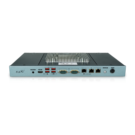
IEI Technology FLEX-BX100-ULT5 Manuals
Manuals and User Guides for IEI Technology FLEX-BX100-ULT5. We have
1
IEI Technology FLEX-BX100-ULT5 manual available for free PDF download: User Manual
IEI Technology FLEX-BX100-ULT5 User Manual (121 pages)
Brand:
IEI Technology
| Category:
Desktop
| Size: 2.77 MB
Table of Contents
Table of Contents
7
1 Introduction
15
Overview
16
Model Variations
16
Figure 1-1: FLEX-BX100-ULT5 Series Box PC
16
Table 1-1: Model Variations
16
Features
17
Front Panel
17
Figure 1-2: Front Panel
17
Rear Panel
18
Top Panel
18
Figure 1-3: Rear Panel
18
Figure 1-4: Top Panel
18
Bottom Panel
19
Figure 1-5: Bottom Panel
19
Technical Specifications
20
Table 1-2: Technical Specifications
21
Dimensions
22
Figure 1-6: Dimensions with Mounting Brackets (MM)
22
2 Unpacking
23
Unpacking
24
Packing List
24
Table 2-1: Package List
25
Optional Items
26
Table 2-2: Optional Items
26
3 Installation
27
Anti-Static Precautions
28
Installation Precautions
28
Installation Procedure
29
Hdd Installation
30
Figure 3-1: HDD Cover Retention Screws
30
Figure 3-2: HDD Bracket Retention Screws
30
Figure 3-3: HDD Retention Screws
31
Figure 3-4: HDD Installation
31
Poe PD Module Installation (Optional)
32
Figure 3-5: Poe Card Cover Retention Screws
32
Figure 3-6: Poe Module Slot Location
32
SSD Installation (Optional)
33
Figure 3-7: Rear Cover Retention Screws
33
Figure 3-8: M.2 Slot Location
34
Figure 3-9: Removing the M.2 Module Retention Screw
34
Figure 3-10: Inserting the M.2 Module into the Slot at an Angle
35
Figure 3-11: Securing the M.2 Module
35
Wireless LAN Module Installation (Optional)
36
Figure 3-12: Knockouts on Rear Panel for Wireless Antennas
36
Figure 3-13: M.2 A-Key Slot Location
36
Figure 3-14: Inserting the WLAN Module
37
Figure 3-15: Securing the WLAN Module
37
Figure 3-16: Connecting RF Cables
38
Figure 3-17: Securing SMA Connector and External Antenna Installation
38
Mounting the System
39
Figure 3-18: Mounting Bracket Retention Screws
39
Figure 3-19: Mounting Bracket Retention Screws
39
Rs-232/422/485 Serial Port (Com1) Selection
40
COM1 Pinouts
40
Table 3-1: RS-232/422/485 Serial Port (COM1) Pinouts
40
COM1 Pin 9 Selection
41
Figure 3-20: COM1 Pin 9 Setting Jumper Location
41
Table 3-2: COM1 Pin 9 Setting Jumper Settings (JP5)
41
At/Atx Mode Selection
42
Clear Cmos
42
Figure 3-21: Clear CMOS Button Location
42
Figure 3-22: AT/ATX Switch Location
42
Power-On Procedure
43
Installation Checklist
43
Figure 3-23: Power Button
43
Figure 3-24: Reset Button Location
44
Figure 3-25: IEI Resource Download Center
44
Driver Download
45
Reset the System
44
Software Installation
44
4 Bios
47
Introduction
48
Starting Setup
48
Using Setup
48
BIOS Menu Bar
49
Getting Help
49
Table 4-1: BIOS Navigation Keys
49
Main
50
Advanced
51
System Date [XX/XX/XX]
51
System Time [XX:XX:XX]
51
CPU Configuration
52
Intel ® (VMX) Virtualization Technology [Disabled]
52
Active Processor Cores [All]
53
Hyper-Threading [Enabled]
53
Intel ® Speedstep™ [Enabled]
53
C State [Disabled]
53
PCH-FW Configuration
54
AMT BIOS Features [Enabled]
54
Unconfigure ME [Disabled]
54
PTT Configuration
55
TPM Device Selection [Dtpm (if Supported)]
55
Trusted Computing
56
Security Device Support [Disable]
56
ACPI Settings
57
ACPI Sleep State [S3 (Suspend to RAM)]
57
RTC Wake Settings
58
Wake System with Fixed Time [Disabled]
58
Iwdd H/W Monitor
59
PC Health Status
59
F81866 Super IO Configuration
60
Serial Port N Configuration
61
Serial Port [Enabled]
61
Device Mode [RS232]
61
Serial Port Console Redirection
62
Serial Port [Enabled]
62
Legacy Console Redirection Settings
63
Console Redirection [Disabled]
63
Legacy Serial Redirection Port [COM1]
63
Console Redirection Settings
64
Terminal Type [ANSI]
64
Bits Per Second [115200]
65
Data Bits [8]
65
Parity [None]
65
USB Configuration
66
Stop Bits [1]
66
USB Devices
66
CSM Configuration
67
Legacy USB Support [Enabled]
67
Nvme Configuration
68
CSM Support [Enabled]
68
IEI Feature
69
Auto Recovery Function [Disabled]
69
Chipset
70
System Agent (SA) Configuration
70
Memory Configuration
71
VT-D [Disabled]
71
Graphics Configuration
72
DVMT Pre-Allocated [32M]
72
DVMT Total Gfx Mem [MAX]
72
PCH-IO Configuration
73
Primary IGFX Boot Display [VBIOS Default]
73
Backlight Control [LED]
73
Restore AC Power Loss [Last State]
74
Power Saving Function(ERP) [Disabled]
74
HD Audio [Enabled]
74
USB Power SW [+5V DUAL]
74
PCI Express Configuration
75
M2_A1 / M2_M2 [Enabled]
75
Pcie Speed [Auto]
75
SATA and RST Configuration
76
Detect Non-Compliance Device [Disabled]
76
STAT Controller(S) [Enabled]
76
SATA Mode Selection [AHCI]
77
Pcie Storage Dev on Port M2_M2 [Not RST Controlled]
77
Security
78
Administrator Password
78
User Password
78
Boot
79
Bootup Numlock State [On]
79
Quiet Boot [Enabled]
80
Launch PXE Oprom [Disabled]
80
Option ROM Messages [Force BIOS]
80
UEFI Boot [Disabled]
80
Boot Option Priority
80
Save & Exit
81
Save Changes and Reset
81
Discard Changes and Reset
81
Restore Defaults
81
Save as User Defaults
81
Restore User Defaults
81
5 Troubleshooting and Maintenance
82
System Maintenance Overview
83
System Troubleshooting
83
The System Doesn't Turn on
83
More Troubleshooting
84
The System Doesn't Boot up
84
Component Replacement
85
6 Interface Connectors
86
Peripheral Interface Connectors
87
Internal Peripheral Connectors
88
Battery Connector (BAT1)
88
Table 6-1: Peripheral Interface Connectors
88
Table 6-2: Battery Connector (BAT1) Pinouts
88
Digital I/O Connector (DIO1)
89
Inverter Connector (INVERTER1)
89
LVDS Connector (LVDS1)
89
Table 6-3: Digital I/O Connector (DIO1) Pinouts
89
Table 6-4: Inverter Connector (INVERTER1) Pinouts
89
A-Key Slot (M2_A1)
90
Table 6-5: LVDS Connector (LVDS1) Pinouts
90
M-Key Slot (M2_M2)
91
Table 6-6: M.2 A-Key Slot (M2_A1) Pinouts
91
Power Button Connector (PWR_BTN2)
93
SATA Connector (SATA1)
93
Table 6-7: M.2 M-Key Slot (M2_M2) Pinouts
93
Table 6-8: Power Button Connector (PWR_BTN2) Pinouts
93
Table 6-9: SATA Connector (SATA1) Pinouts
93
Smbus Connector (SMB1)
94
SPI Flash Connector (JSPI1)
94
Table 6-10: Smbus Connector (SMB1) Pinouts
94
Table 6-11: SPI Flash Connector (JSPI1) Pinouts
94
Table 6-12: USB Connector (TOUCH_USB1) Pinouts
94
USB Connector (TOUCH_USB1)
94
USB Connector (EXT_USB1)
95
External Interface Panel Connectors
95
Table 6-13: USB Connector (EXT_USB1) Pinouts
95
Table 6-14: External Connectors
95
Ethernet Connectors (LAN1, J1, J2)
96
HDMI Connector (HDMI1)
96
Table 6-15: Ethernet Connectors (LAN1, J1, J2) Pinouts
96
Table 6-16: Ethernet Connector Leds
96
Table 6-17: HDMI Connector (HDMI1) Pinouts
96
Power Connector (PWR3)
97
RJ-45 Serial Port (COM2)
97
RS-232/422/485 DB-9 Serial Port (COM1)
97
Table 6-18: Power Connector (PWR3) Pinouts
97
Table 6-19: RS-232/422/485 DB-9 Serial Port (COM1) Pinouts
97
Table 6-20: RS-232 RJ-45 Serial Port (COM2) Pinouts
97
USB 3.2 Gen 2 Connectors (USB_CON1, USB_CON2)
98
Jumpers
98
Flash Descriptor Security Override Jumper
98
Table 6-21: USB 3.2 Gen 2 Connectors (USB_CON1, USB_CON2) Pinouts
98
Table 6-22: Jumpers
98
Table 6-23: Flash Descriptor Security Override Jumper Settings
99
A Regulatory Compliance
100
B Safety Precautions
105
Safety Precautions
106
General Safety Precautions
106
Anti-Static Precautions
107
Product Disposal
108
Maintenance and Cleaning Precautions
109
Cleaning Tools
109
Maintenance and Cleaning
109
CBIOS Menu Options
111
C.1 BIOS Configuration Options
112
Bios Configuration Options
112
D Watchdog Timer
114
E Error Beep Code
117
Pei Beep Codes
118
Dxe Beep Codes
118
F Hazardous Materials Disclosure
119
Rohs II Directive (2015/863/EU)
120
China Rohs
121
Advertisement
Advertisement
Related Products
IEI Technology FLEX-BX200AI
IEI Technology FLEX-BX200-Q370/25
IEI Technology FLEX-BX200-Q370-P/25
IEI Technology FLEX-BX200-Q370-i3/25
IEI Technology FLEX-BX200-Q370/35
IEI Technology FLEX-BX200-Q370-P/35
IEI Technology FLEX-BX200-Q370-i3/35
IEI Technology FLEX-BX200-Q370-i7/35
IEI Technology FLEX-BX210
IEI Technology FLEX-BX200-Q370-i5/35
IEI Technology Categories
Motherboard
Touch Panel
Computer Hardware
Single board computers
Desktop
More IEI Technology Manuals
Login
Sign In
OR
Sign in with Facebook
Sign in with Google
Upload manual
Upload from disk
Upload from URL