LinMot B1100-PP Installation Manual
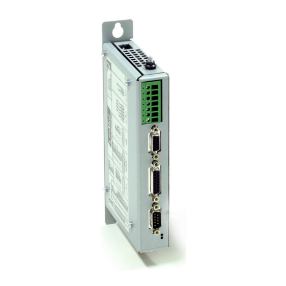
Servo controller
Hide thumbs
Also See for B1100-PP:
- Quick start manual (17 pages) ,
- Installation manual (18 pages) ,
- Installation manual (19 pages)

Related Manuals for LinMot B1100-PP


Summary of Contents for LinMot B1100-PP
- Page 1 Installation Documentation for the following Controllers: B1100-PP (-HC, -XC) B1100-VF (-HC, -XC) B1100-GP (-HC, -XC) Servo Controller Installation Guide Document version: 3.9.2 / June 2009...
- Page 2 Under the copyright laws, this publication may not be reproduced or transmitted in any form, electronic or mechanical, including photocopying, recording, microfilm, storing in an information retrieval system, not even for didactical use, or translating, in whole or in part, without the prior written consent of NTI AG. LinMot ® is a registered trademark of NTI AG.
-
Page 3: Table Of Contents
IMPORTANT NOTES FOR B1100 SERIES CONTROLLERS........4 SYSTEM OVERVIEW.....................5 B1100 INTERFACES......................6 FUNCTIONALITY......................7 SOFTWARE........................7 POWER SUPPLY AND GROUNDING................8 DESCRIPTION OF THE CONNECTORS / INTERFACES..........9 PHYSICAL DIMENSION....................14 POWER SUPPLY REQUIREMENT................15 ORDERING INFORMATION..................16 INTERNATIONAL CERTIFICATIONS................16 DECLARATION OF CONFORMITY CE-MARKING............17 CONTACT ADDRESSES.....................18 NTI AG, LinMot Installation Guide B1100 Page 3/18... -
Page 4: Important Notes For B1100 Series Controllers
All connectors must not be con nected or disconnected while DC voltage is present. Do not disconnect system components until all LinMot controllers LEDs have turned off. (Capacitors in the power supply may not fully discharge for several minutes after input voltage has been disconnected). -
Page 5: System Overview
Installation Guide B1100 System Overview Typical servo system B1100-XX-YY: Servo controller, motor and power supply. NTI AG, LinMot Installation Guide B1100 Page 5/18... -
Page 6: B1100 Interfaces
6 Digital Outputs Analog In 0..10V ● ● ● Analog In –10V.. +10V Diff Step Dir zero 24V Logic Supply State Indicator ● ● ● Bus Termination ● ● ● Page 6 of 18 Installation Guide B1100 NTI AG/ LinMot/... -
Page 7: Functionality
● ● ● Software The configuration SW LinMotTalk1100 is free of charge and can be downloaded from our home page. For fast results see also the quick start guides and configurations for the B1100-PP and B1100-VF controllers: • QuickStartGuide_B1100-PP.pdf •... -
Page 8: Power Supply And Grounding
In order to assure a safe and error free operation, and to avoid severe damage to system components, all system components* must be well grounded to either a single earth or utility ground. This includes both LinMot and all other control system components to the same ground bus. -
Page 9: Description Of The Connectors / Interfaces
RMS current is below 2A and peak current is below 4A. Never connect motor phases on X2 and X3! - Tightening Torque: min 0.4Nm - Screw Thread: M 2,5 - Conductor Cross-Section: max. 2.5mm - Use 60/75°C copper conductors only NTI AG, LinMot Installation Guide B1100 Page 9/18... - Page 10 Installation Guide B1100 Motor LinMot Motor: 3-phase EC-Motor: Motor Phase 1+ Motor Phase 2+ +5VDC +5VDC (Hall Supply) Sensor Sine Hall 1 Temp. In Hall 3 Motor Phase 1- Motor Phase 2- AGND AGND (Hall Supply) Sensor Cosine Hall 2...
- Page 11 S 4 . 2 S 4 . 3 RS485_Rx+ RS485_Rx- RS485_Tx- CAN_L CAN_H case Shield DSUB-9 (m) RS232: Configuration on all controllers: use 1:1 connection cable to PC X7 - X8 RS485/CAN NTI AG, LinMot Installation Guide B1100 Page 11/18...
- Page 12 Max Output Frequency: 2.5MHz, 5 M counts/s with quadrature decoding, 200ns edge separation Differential Hall Switch Inputs: RS422 Input Frequency: <1kHz Enc. Alarm In: 5V / 1mA Sensor Supply: 5VDC max 100mA X14: 24VDC Supply and IOs Page 12 of 18 Installation Guide B1100 NTI AG/ LinMot/...
- Page 13 Indexer Inputs: RS422, Max. Input Frequency: 2MHz, 4 M counts/s with quadrature decoding, 240ns edge separation If an input is used as a trigger input, the sampling rate is set to 200us. NTI AG, LinMot Installation Guide B1100 Page 13/18...
-
Page 14: Physical Dimension
40…50 with power derating Relative humidity 95% (non-condensing) Max. Case Temperature °C Max. Power Dissipation Distance between mm (in) 20 (0.8) horizontal Controllers 50 (2) vertical ( ) dimensions in inch Page 14 of 18 Installation Guide B1100 NTI AG/ LinMot/... -
Page 15: Power Supply Requirement
(all 6 outputs “on” with 50mA load and /Break with no load) Max. 1.2A (all 6 outputs “on” with 100mA load and /Break with 0.5A load) To limit the power in case of malfunction, it is recommended to use an external fuse (2AT). NTI AG, LinMot Installation Guide B1100 Page 15/18... -
Page 16: Ordering Information
B1100-GP General Purpose Controller 72VDC/8A 0150-1737 B1100-GP-HC General Purpose Controller 72VDC/15A 0150-1738 B1100-GP-XC General Purpose Controller 72VDC/25A 0150-1741 B1100-PP Point to Point Controller 72VDC/8A 0150-1735 B1100-PP-HC Point to Point Controller 72VDC/15A 0150-1736 B1100-PP-XC Point to Point Controller 72VDC/25A 0150-1740 B1100-VF... -
Page 17: Declaration Of Conformity Ce-Marking
Class A Conducted radio frequency immunity EN 61000-6-4 Emission for industrial environment EN 55022 Class A Radiated Emission Company NTI Ltd. Zurich, September 20, 2007 ----------------------------------------------------------- R. Rohner / CEO NTI AG NTI AG, LinMot Installation Guide B1100 Page 17/18... -
Page 18: Contact Addresses
+41-(0)56-419 91 91 office@linmot.com Tech. Support: +41-(0)56-544 71 00 support@linmot.com Tech. Support (Skype) : skype:support.linmot Fax: +41-(0)56-419 91 92 Web: http://www.linmot.com/ ----------------------------------------------------------------------------------------------------------------------------- LinMot, Inc. N5750 Townline Road Elkhorn, WI 53121 Sales and Administration: 877-546-3270 262-743-2555 Tech. Support: 877-804-0718 262-743-1284 Fax: 800-463-8708 262-723-6688 E-Mail: us-sales@linmot.com...