
Related Manuals for LinMot E1200-GP-UC


Summary of Contents for LinMot E1200-GP-UC
- Page 1 Documentation for installing the following Controllers: E1200-GP-UC E1230-DP-UC E1250-PL-UC E1250-EC-UC E1250-PN-UC E1250-IP-UC E1250-SC-UC Servo Controller Data Sheet & Installation Guide...
- Page 2 NTI AG. ® LinMot is a registered trademark of NTI AG. Note The information in this documentation reflects the stage of development at the time of press and is therefore without obligation.
-
Page 3: Table Of Contents
PHYSICAL DIMENSION......................12 POWER SUPPLY REQUIREMENTS .................. 13 REGENERATION OF POWER / REGENERATION RESISTOR........13 ORDERING INFORMATION ....................14 INTERNATIONAL CERTIFICATIONS................. 14 DECLARATION OF CONFORMITY CE-MARKING ............15 CONTACT ADDRESSES ...................... 16 NTI AG, LinMot Installation Guide E1200 05/01/2010 Page 3/16... -
Page 4: Important Safety Notes For E1200 Series Controllers
All connectors must not be connected or disconnected while DC voltage is present. Do not disconnect system components until all LinMot controller LED’s have turned off. (Capacitors in the power supply may not fully discharge for several minutes after input voltage has been disconnected). -
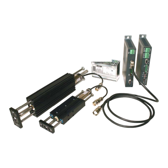
Page 5: System Overview
MASTER ENCODER STEP+ STEP+ MASTER ENCODER STEP- STEP- DIRECTION+ DIRECTION+ ZERO+ ZERO+ ZERO- ZERO- DIRECTION- DIRECTION- CAN_H CAN_H CAN_L CAN_L Typical Servo System E12x0-XX: Servo Controller, Linear Motor and Power Supply. NTI AG, LinMot Installation Guide E1200 05/01/2010 Page 5/16... -
Page 6: Functionality And Interfaces
● ● ● ● ● ● ● Motor Phase Current / 12A ● ● ● ● ● ● ● peak Controllable Motors LinMot P01-23x… ● ● ● ● ● ● ● P01-37x… ● ● ● ● ● ● ● P01-48x…... -
Page 7: Power Supply And Grounding
In order to assure a safe and error free operation, and to avoid severe damage to system components, all system components* must be well grounded to either a single earth or utility ground. This includes both LinMot and all other control system components to the same ground bus. -
Page 8: Description Of The Connectors / Interfaces
- Use 60/75°C copper conductors only - Conductor cross-section: 2.5 - 4mm / AWG 14 – 12, if possible, use 4mm - Stripping length: 14mm - Max. length: 4m Motor Phases LinMot Motor: 3-phase EC-Motor: PH1+ /U Motor Phase 1+ Motor Phase U PH1- /V... - Page 9 Yellow Motor Enabled / Error Code Low Nibble Yellow Warning / Error Code High Nibble Error S1, S2: Baud Rate / Address Selectors Bus ID High (0…F) Bus ID Low (0…F) NTI AG, LinMot Installation Guide E1200 05/01/2010 Page 9/16...
- Page 10 Shield Analog In (+-10V Differential Analog Input) Reserved, do not connect Reserved, do not connect Analog In- Analog In+ Reserved, do not connect Reserved, do not connect case Shield Page 10 of 16 Installation Guide E1200 05.01.2010 NTI AG/ LinMot/...
- Page 11 Use twisted pair (1-2, 3-6, 4-5, 7-8) cable for wiring. The built in CAN and RS485 terminations can be activated by S5.3 and S5.2. X7 is internally connected to X8 (1:1 connection) NTI AG, LinMot Installation Guide E1200 05/01/2010 Page 11/16...
-
Page 12: Error Codes
High Nibble Low Nibble The meaning of the Error Codes can be found in the Usermanual_MotionCtrl_Software_E1200 and the user manual of the loaded interface software. These documents are provided together with LinMot-Talk www.linmot.com E1100 and can be downloaded from Physical Dimension... -
Page 13: Power Supply Requirements
S01-72/500 72VDC, 10A peak, 500VA, 1x120/230VAC 0150-1874 For compatibility with other power supplies, contact support@linmot.com Signal Power Supply The logic supply needs a regulated power supply of a nominal voltage of 24 VDC. The voltage must be between 22 and 26 VDC. -
Page 14: Ordering Information
E1250-SC-UC SERCOS III Servo Controller 72VDC/32A 0150-1764 E1250-IP-UC ETHERNET IP Servo Controller 72VDC/32A 0150-1761 E1230-DP-UC PROFIBUS-DP Servo Controller 72VDC/32A 0150-1766 E1200-GP-UC GENERAL PURPOSE Servo Controller 72VDC/32A 0150-1771 Adaptercable for AC01-RJ45/Df-2.5-RS1 (0150-2143) 0150-2143 Configuration over RS232 (on X19) International Certifications Certifications... -
Page 15: Declaration Of Conformity Ce-Marking
Class A Conducted radio frequency immunity EN 61000-6-4 Emission for industrial environment EN 55022 Class A Radiated Emission Company NTI Ltd. Zurich, June 16, 2009 ----------------------------------------------------------- R. Rohner / CEO NTI AG NTI AG, LinMot Installation Guide E1200 05/01/2010 Page 15/16... -
Page 16: Contact Addresses
Sales and Administration: office@linmot.com +41-(0)56-544 71 00 Tech. Support: support@linmot.com skype:support.linmot Tech. Support (Skype): +41-(0)56-419 91 92 Fax: http://www.linmot.com/ Web: LinMot, Inc. 5750 Townline Road Elkhorn, WI 53121 877-546-3270 Sales and Administration: 262-743-2555 877-804-0718 Tech. Support: 262-743-1284 800-463-8708 Fax: 262-723-6688 sales@linmot-usa.com...
Need help?
Do you have a question about the E1200-GP-UC and is the answer not in the manual?
Questions and answers