LinMot B1100-PP Installation Manual
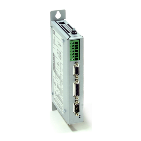
Servo controller
Hide thumbs
Also See for B1100-PP:
- Quick start manual (17 pages) ,
- Installation manual (18 pages) ,
- Installation manual (18 pages)
Table of Contents
Advertisement
Quick Links
B1100 Servo Controller
Installation Guide
Eine Deutsche Version kann unter http://www.linmot.com bezogen werden!
Please visit http://www.linmot.com to check for the latest version of this document!
This document applies to the following controllers:
B1100-PP (-HC, -XC)
B1100-VF (-HC, -XC)
B1100-GP (-HC, -XC)
Advertisement
Table of Contents

Related Manuals for LinMot B1100-PP


Summary of Contents for LinMot B1100-PP
- Page 1 B1100 Servo Controller Installation Guide Eine Deutsche Version kann unter http://www.linmot.com bezogen werden! Please visit http://www.linmot.com to check for the latest version of this document! This document applies to the following controllers: B1100-PP (-HC, -XC) B1100-VF (-HC, -XC) B1100-GP (-HC, -XC)
- Page 2 NTI AG. LinMot® is a registered trademark of NTI AG. The information in this documentation reflects the stage of development at the time of press and is therefore without obligation.
-
Page 3: Table Of Contents
7.5 X7 - X8........................12 7.6 X13..........................12 7.7 X14..........................13 7.8 LEDs.........................14 7.9 S4..........................14 8 Physical Dimension.......................15 9 Power Supply Requirement..................16 10 Ordering Information....................17 11 International Certifications..................17 12 Declaration of Conformity CE-Marking..............18 13 Contact Addresses......................19 ® NTI AG / LinMot www.LinMot.com Page 3/19... -
Page 4: Important Safety Notes For B1100 Series Controllers
E-Stop breaks should be done to the AC supply voltage of the power supply. Do not connect or disconnect the motors from controllers while voltage is applied. Wait to connect or disconnect motors until all LinMot controllers LEDs have turned off. (Capacitors may not fully discharge for several... -
Page 5: System Overview
LinMot Installation Guide 2 System Overview Typical servo system B1100-XX-YY: Servo controller, motor and power supply. ® NTI AG / LinMot www.LinMot.com Page 5/19... -
Page 6: B1100 Interfaces
6 Digital Inputs 6 Digital Outputs Analog In 0..10V ● ● ● Analog In –10V.. +10V Diff Step Dir zero 24V Logic Supply State Indicator ● ● ● Bus Termination ● ● ● ® NTI AG / LinMot www.LinMot.com Page 6/19... -
Page 7: Functionality
● 5 Software The configuration software LinMot-Talk is free of charge and can be downloaded from the LinMot homepage. For fast results see also the quick start guides and configurations for the B1100-PP and B1100-VF controllers: • QuickStartGuide_B1100-PP.pdf • QuickStartGuide_B1100-VF.pdf This quick start guides are distributed with the LinMot-Talk software. -
Page 8: Power Supply And Grounding
In order to assure a safe and error free operation and to avoid severe damage to system components, all system components* must be well grounded to either a single earth or utility ground. This includes both LinMot and all other control system components to the same ground bus. -
Page 9: Description Of The Connectors / Interfaces
Never connect motor phases on X2 and X3! - Tightening Torque: min 0.4Nm - Screw Thread: M 2,5 - Conductor Cross-: max. 2.5mm (AWG14), Length < 30m - Use 60/75°C copper conductors only ® NTI AG / LinMot www.LinMot.com Page 9/19... - Page 10 Motor Wiring for Phase Currents above 2A RMS or 4A peak (recommended general wiring) Important: If motor phase current exceeds 2A or 4A , motor phases must be wired to X2! peak ® NTI AG / LinMot www.LinMot.com Page 10/19...
- Page 11 Shield DSUB-9 (m) RS232: Configuration on all controllers: use 1:1 connection cable to PC with only pins 2,3 and 5 connected. Use LinMot RS configuration cable (Art.-No. 0150-3307). Cable length < 30m. ® NTI AG / LinMot www.LinMot.com Page 11/19...
-
Page 12: X7 - X8
Max Output Frequency: 2.5MHz, 5 M counts/s with quadrature decoding, 200ns edge separation Differential Hall Switch Inputs (RS422): Input Frequency: <1kHz Enc. Alarm In: 5V / 1mA Sensor Supply: 5VDC max 100mA Cable length < 30m. ® NTI AG / LinMot www.LinMot.com Page 12/19... -
Page 13: X14
Differential Analog Input on X14.8 X14.21 X14.9 Shield: Range: -10V..+10V 10Bit ADC Sample Rate: 400us Differential Step Dir Zero: Indexer Inputs: RS422, Max. Input Frequency: 2MHz, 4 M counts/s with quadrature decoding, 240ns edge separation Cable length < 30m. ® NTI AG / LinMot www.LinMot.com Page 13/19... -
Page 14: Leds
Switch 3: Termination CAN on/off Switch 2: Termination RS485 on/off Switch 1: RS232 (switch “off” / RS485 “on”). Selection for RS232 or RS485 Factory settings: Switch 3 “on”, all other switches “off” ® NTI AG / LinMot www.LinMot.com Page 14/19... -
Page 15: Physical Dimension
0…40 at rated data 40…50 with power derating Relative humidity 95% (non-condensing) Max. Case Temperature °C Max. Power Dissipation Distance between mm (in) 20 (0.8) horizontal Controllers 50 (2) vertical ( ) dimensions in inch ® NTI AG / LinMot www.LinMot.com Page 15/19... -
Page 16: Power Supply Requirement
(all 6 outputs “on” with 50mA load and /Break with no load) Max. 1.2A (all 6 outputs “on” with 100mA load and /Break with 0.5A load) To limit the power in case of malfunction, it is required to use an external fuse (2AT)! ® NTI AG / LinMot www.LinMot.com Page 16/19... -
Page 17: Ordering Information
Current Command Controller 72VDC/25A 0150-1739 Accessories Description Art. No. RS232 Config AC01-Df/Df-2-RS1 0150-3307 Cable RS232 Config Cable DSUB9 f/f 2m (2-2/3-3/5-5) 11 International Certifications Certifications Europe See chapter “Declaration of Conformity CE-Marking“ ® NTI AG / LinMot www.LinMot.com Page 17/19... -
Page 18: Declaration Of Conformity Ce-Marking
LinMot Installation Guide 12 Declaration of Conformity CE-Marking Manufacturer: NTI AG / LinMot ® Haerdlistrasse 15 8957 Spreitenbach Switzerland Tel.: +41 (0)56 419 91 91 Fax: +41 (0)56 419 91 92 Products: LinMot ® Controllers Type Art.-No. Type Art-No. Type Art.-No. -
Page 19: Contact Addresses
Elkhorn, WI 53121 Sales and Administration: 877-546-3270 262-743-2555 Tech. Support: 877-804-0718 262-743-1284 Fax: 800-463-8708 262-723-6688 E-Mail: us-sales@linmot.com Web: http://www.linmot-usa.com/ Please visit http://www.linmot.com/ to find the distributor closest to you. Smart solutions are… ® NTI AG / LinMot www.LinMot.com Page 19/19...
Need help?
Do you have a question about the B1100-PP and is the answer not in the manual?
Questions and answers