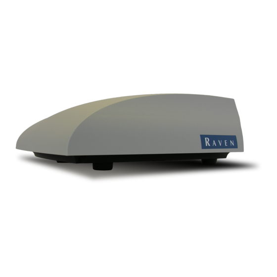
Raven RS1 Installation Manual
Iso guidance and steering for rogator b
Hide thumbs
Also See for RS1:
- Calibration and operation manual (125 pages) ,
- Calibration & operation manual (100 pages) ,
- Installation manual (84 pages)
Advertisement
Quick Links
ROGATOR B RAVEN RS1™ ISO GUIDANCE AND STEERING INSTALLATION GUIDE
ROGATOR B RAVEN RS1™ ISO GUIDANCE AND
STEERING INSTALLATION GUIDE
This quick guide provides the installation instructions for the RS1 on an ISO Rogator B series machine. For
calibration and operation information, refer to the Operation Manual (P/N 016-4010-001).
The RS1 is an all-in-one unit that provides GPS, guidance, and cellular connectivity.
INSTALLATION DIAGRAM
The image below provides a basic overview of the installation of the RS1. Refer to the next sections for detailed
installation information.
Manual No. 016-5033-150 Rev C1 EC31824 08/18
1
Advertisement

Subscribe to Our Youtube Channel
Summary of Contents for Raven RS1
- Page 1 The RS1 is an all-in-one unit that provides GPS, guidance, and cellular connectivity. INSTALLATION DIAGRAM The image below provides a basic overview of the installation of the RS1. Refer to the next sections for detailed installation information. Manual No. 016-5033-150 Rev C1 EC31824 08/18...
- Page 2 FIGURE 1. RS1 RoGator B Series Installation Diagram RoGator B Raven RS1™ ISO Guidance and Steering Installation Guide...
- Page 3 ROGATOR B RAVEN RS1™ ISO GUIDANCE AND STEERING INSTALLATION GUIDE RS1 UNIT INSTALLATION For RS1 to operate, the RS1 unit must be mounted on the cab roof. To install the unit: 1. Remove the seven bolts that secure the roof cap to the cab frame.
- Page 4 FIGURE 5. CAN Loop Back Cable 7. Remove the CAN loop back cable and save for future use. 8. In the radio opening, connect the 12-pin Deutsch connector on the RS1 cable (P/N 115-4010-010) to the machine’s 12-pin CAN connector.
- Page 5 13. Feed the 8-pin connector labeled “Engage” down the corner post and into the opening below the cup-holder in the rear-right corner. 14. Carefully push the cable RS1 cable assembly into the radio opening and replace the radio cover. 15. Locate and remove the corner access panel on the outside of the cab.
- Page 6 21. Reinstall, but do not tighten, the front three bolts that secure the top of the cab to the frame. 22. Assemble the latch, plug, rubber washer, and latch nut through the latch hole on RS1 mounting plate. FIGURE 10. Latch Assembly...
- Page 7 Latch Bracket 25.Place the RS1 unit roof bracket on the cab with it oriented as shown in Figure 13 on page 8. The holes on the corners of the roof bracket will line up with existing cab top mounting holes.
- Page 8 FIGURE 14. RS1 Unit Orientation Latch Handle Towards Machine Front 29. Connect the 12-pin Deutsch connector on the 115-4010-010 cable to the mating receptacle on the RS1 unit. FIGURE 15. Cabling Connection on RS1 Unit Cellular Antenna (if...
- Page 9 ROGATOR B RAVEN RS1™ ISO GUIDANCE AND STEERING INSTALLATION GUIDE 30. If applicable, connect the cellular antenna to the back of the RS1 unit and secure the antenna to the roof bracket using the magnet attached to the antenna. FOR MY 15 AND OLDER MACHINES 1.
- Page 10 3. Ensure the two 2-pin Deutsch ISO CAN connectors on the Viper 4 ISO CAN harness are connected to each other and are not plugged into dust caps. FIGURE 19. 2-Pin Deustch Connectors RoGator B Raven RS1™ ISO Guidance and Steering Installation Guide...
-
Page 11: Operation
OPERATION Refer to the RS1 Calibration and Operation Manual (P/N 016-4010-001) for instructions on configuring, calibrating, and operating RS1. Please note the location of the master switch and the foot pedal on the machine because they are needed for operation. - Page 12 RoGator B Raven RS1™ ISO Guidance and Steering Installation Guide...


Need help?
Do you have a question about the RS1 and is the answer not in the manual?
Questions and answers