
Related Manuals for Eaton PXR10


Summary of Contents for Eaton PXR10
- Page 1 Manual 01/21 MN012005EN PXR10, PXR20, PXR25 Electronic trip unit Power Xpert Release PXR for NZM... circuit breakers...
- Page 2 All editions of this document other than those in German language are translations of the original operating manual. published 2019, edition date 07/2019 published 2021, edition date 01/2021 See revision protocol in the “About this manual“ chapter. © 2019 by Eaton Industries GmbH, 53105 Bonn Authors: Daniel Jansen, Camilla Abreu Editing: René Wiegand All rights reserved, also for the translation.
- Page 3 Danger! Dangerous electrical voltage! Before commencing the installation • Disconnect the power supply of the device. • Wherever faults in the automation system may cause damage to persons or property, external measures must • Ensure that devices cannot be accidentally retriggered. be implemented to ensure a safe operating state in the •...
-
Page 5: Table Of Contents
Standards, guidelines, approvals..........10 Design ..................11 Operator interface ................ 12 2.1.1 Rotary switch on the PXR10 and PXR20 trip units....... 12 2.1.2 LCD display on the PXR25 trip units ..........13 Micro-USB connection ..............15 LED Status indication ..............16 Trip reason indicator.............. - Page 6 Interface module................41 Relay module ................43 Testing the trip unit and the circuit breaker ......47 Testing (remote) of the circuit-breaker via USB/PXPM ....48 Testing the ground-fault releases - primary injection ....48 PXR Electronic trip unit 01/21 MN012005EN www.eaton.com...
- Page 7 Date and time................74 9.3.9 Internal diagnostics ..............75 9.3.10 Primary status codes..............76 9.3.11 Secondary status codes ............... 76 9.3.12 Reason codes................76 9.3.13 Device information ............... 77 9.3.14 Exception codes................78 PXR Electronic trip unit 01/21 MN012005EN www.eaton.com...
- Page 8 Configuration of the Modbus parameters........133 10.3.2 IP configuration/DIP Switch Settings ........... 134 10.3.3 Profinet (GSDML file)..............135 10.3.4 Profinet register map ..............135 Troubleshooting................. 159 PXR25 Navigation menu ............161 Alphabetical index ..............165 PXR Electronic trip unit 01/21 MN012005EN www.eaton.com...
-
Page 9: About This Manual
0.1 List of revisions 0 About this manual This manual covers the PXR10, PXR20 and PXR25 electronic trip units of the NZM digital circuit breaker as well as the relevant accessories. The manual describes the various versions of the product series, as well as their installation and operation. -
Page 10: Abbreviations And Symbols
Zone selective interlocking → The abbreviation PXR: For the PXR10, PXR20 and PXR25 versions, the abbreviation PXR is used if a statement applies equally to all three. The symbols used in this manual have the following meanings: ▶ indicates an action to be taken. -
Page 11: Safety Warning Concerning Property Damage
Indicates a potentially hazardous situation that may result in death or serious injury DANGER Indicates an imminently hazardous situation that will result in death or serious injury 0.3.3 Tips → Indicates useful tips. PXR Electronic trip unit 01/21 MN012005EN www.eaton.com... -
Page 12: Additional Documents
White paper on live electrical circuits” “Improved lifecycle management White paper thanks to digital circuit protection” “xSpider” Software www.eaton.com/xspider (graphical design system for the planning of low-voltage networks) “Power Xpert Protection Manager” Software www.eaton.com/PXPM PXR Electronic trip unit 01/21 MN012005EN www.eaton.com... -
Page 13: Function
NZM4 series) consists of current sensors and a trip actuator in conjunction with the PXR (Power Xpert Release) electronic trip. The electronic trip units PXR10, PXR20 and PXR25 in particular ensure the protection function of the circuit breaker. In addition to its main function (= protection), the PXR electronic trip unit makes it possible •... -
Page 14: Standards, Guidelines, Approvals
The PXR trip units are also certified for use in the NZM...NA series circuit breakers by Underwriters Laboratories Inc. (UL) and the Canadian Standards Association (CSA). → Further information on the NZM digital circuit breakers can be found on the Eaton website: www.eaton.com/digitalNZM PXR Electronic trip unit 01/21 MN012005EN www.eaton.com... -
Page 15: Design
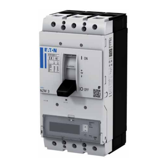
NZM circuit breaker with PXR trip unit Please note: The operator interfaces of the trip units differ from one another: The PXR10 and PXR20 versions are fitted with rotary switches, while on the PXR25 version, an LCD display is used for indicating and adjusting the settings. -
Page 16: Operator Interface
2 Design 2.1 Operator interface 2.1 Operator interface 2.1.1 Rotary switch on the PXR10 and PXR20 trip units Depending on the type of trip unit, there are up to seven rotary switches at the front of the unit. 6.5 7 7.5 11 12 13 0.2 0.3... -
Page 17: Lcd Display On The Pxr25 Trip Units
The following languages are pre-installed: • English • German • French • Italian • Polish • Dutch • Norwegian • Swedish → Additional language packs can be installed via the Power Xpert Protection Manager configuration software. PXR Electronic trip unit 01/21 MN012005EN www.eaton.com... - Page 18 The status LED indicates if the trip unit is ready for operation. During normal operation, this LED will flash green. → Also see → chapter 12, “PXR25 Navigation menu”, page 161 for a graphical representation of the navigation menu. PXR Electronic trip unit 01/21 MN012005EN www.eaton.com...
-
Page 19: Micro-Usb Connection
Standard Micro-USB on USB-A cable Temporary connection for using the Power Xpert Protection Manager Standard Micro-USB power bank To establish a temporary connection for supplying power to the trip unit if the unit is not self-supplying. PXR Electronic trip unit 01/21 MN012005EN www.eaton.com... -
Page 20: Led Status Indication
This therefore does not constitute a malfunction. The Status LED will flash again if the auxiliary power supply is activated, or if the load on the circuit breaker rises to a level greater than 15 %. PXR Electronic trip unit 01/21 MN012005EN www.eaton.com... -
Page 21: Trip Reason Indicator
2.4 Trip reason indicator 2.4 Trip reason indicator PXR10 The PXR10 trip units are not equipped with any indicators. PXR20 The PXR20 trip units are equipped with up to four trip-reason indicators at the front. These indicators are marked LONG, SHORT, INST and GND. -
Page 22: Overload Indicator
2.5 Overload indicator 2.5 Overload indicator PXR10, PXR20 The PXR10 and PXR20 trip units are equipped with an orange overload LED for load and overload warnings, which are triggered at 85 % (LED on) and 105 % (LED flashing) of I , respectively. -
Page 23: Protection And Measurement Functions
-VX…-T(-NA) ✓ ✓ ✓ ✓ ✓ ✓ ✓ PXR25 -PX(-NA) ✓ ✓ ✓ ✓ ✓ – – -PXM(-NA) ✓ ✓ – – ✓ – – -PX...-TZ(TAZ)(-NA) ✓ ✓ ✓ ✓ ✓ ✓ ✓ PXR Electronic trip unit 01/21 MN012005EN www.eaton.com... - Page 24 Eaton publication “Setting-specific representation of tripping characteristics and competent assessment of their interaction”, which is available for download on the Eaton website: www.eaton.eu/ecm/groups/public/@pub/@europe/@electrical/documents/content/pct_998455_de.pdf → The xSpider software is available on the Eaton website at www.xspider.eaton.eu PXR Electronic trip unit 01/21 MN012005EN www.eaton.com...
-
Page 25: Measuring Functions
Maximum VL1-N, VL2-N, VL3-N Group values are held until reset 1) PXR10 / PXR20: Accuracy of current measurement: 5 % valid for 40 % to 100 % of I PXR25: Accuracy of measurement: 0.5 % Current measurement: valid for 10 % to 120 % of I at 25 °C (77 °F) -
Page 26: Power And Energy Measurements
Total reactive energy kvarh “Reactive energy (forward)” + “reactive energy (reverse)” 1) Accuracy: Class 1 (derived from IEC61557-12) The power and energy values are calculated and updated internally at a frequency of 1 Hz. PXR Electronic trip unit 01/21 MN012005EN www.eaton.com... -
Page 27: Time/Current Characteristics
3.5 Time/current characteristics 3.5 Time/current characteristics The time/current characteristics of the PXR trip units on the NZM circuit breakers can be found in Eaton’s xSpider software via the link listed below. → The xSpider software is available on the Eaton website at: www.xspider.eaton.eu... - Page 28 3 Protection and measurement functions 3.6 Voltage tap of the neutral conductor on the PXR25 L1 L2 L3 Figure 6: Connecting the N conductor on the NZM4 PXR Electronic trip unit 01/21 MN012005EN www.eaton.com...
-
Page 29: Protection Settings
Ground-fault trip I • Ground-fault delay time t The settings can be adjusted using the rotary switches (on the PXR10 and PXR20 trip units) or the display (on the PXR25 trip unit) at the front of the trip unit. Additional options can be selected via the display (on the PXR25 trip unit only), the navigation buttons, the Power Xpert Protection Manager configuration software (on all PXR variants) or the communication link. -
Page 30: Overload Pre-Warning
This function enables the circuit breaker to protect both downstream cables (outgoing cables) and equipment as well as its own integrity against excessive heating in the event of repeated overcurrents. PXR Electronic trip unit 01/21 MN012005EN www.eaton.com... -
Page 31: Short-Time Delayed Short-Circuit Release
A ground-fault alarm ensures early warning in the event of a ground fault, while a ground-fault trip provides protection in this case. The following three modes of operation can be selected. PXR Electronic trip unit 01/21 MN012005EN www.eaton.com... - Page 32 If a 3-pole circuit breaker is used in a neutral network, the neutral current will not be detected. In this case, a ground-fault trip may occur if the threshold values of the ground-fault release are exceeded. PXR Electronic trip unit 01/21 MN012005EN www.eaton.com...
-
Page 33: Instantaneous Release (Override)
4.8 Digital bypass Should the main processor malfunction, the secondary processor will take over at 1.2 x I If the value exceeds 1.2 x I , the circuit breaker will trip immediately. PXR Electronic trip unit 01/21 MN012005EN www.eaton.com... -
Page 34: Maintenance Mode (Arms)
4.9 Maintenance mode (ARMS) 4.9 Maintenance mode (ARMS) The PXR25 trip units support Eaton’s Arc Flash Reduction Maintenance System™ (ARMS). This is also known as the maintenance mode. If enabled, the trip unit will trip the circuit breaker with no intentional delay whenever the configured threshold value is exceeded. -
Page 35: Zone Selective Interlocking (Zsi)
This restraining signal will cause all upstream circuit breakers to continue operating with their own coordination delays, to ensure that the supply is only interrupted locally. Figure 8: ZSI circuits PXR Electronic trip unit 01/21 MN012005EN www.eaton.com... -
Page 36: Event Logging And Waveform Capture
Zone Out (Z • Zone Common (Z These signals are compatible with all Eaton circuit breakers that have the ZSI function. An output signal will be transmitted each time the ground-fault threshold or the short-time delay threshold is exceeded. This provides maximum selectivity for coordination with larger upstream circuit breakers. - Page 37 Trip - short-time delayed ✓ ✓ ✓ Trip - instantaneous ✓ ✓ ✓ Trip - ground fault ✓ ✓ ✓ Trip - maintenance mode ✓ ✓ ✓ Trip - neutral conductor ✓ ✓ ✓ PXR Electronic trip unit 01/21 MN012005EN www.eaton.com...
- Page 38 L2-L3 • (VCA) L3-L1 • (VAN) L1-N • (VBN) L2-N • (VCN) L3-N 6 cycles (384 data points) → To use event logging in all operating states, an external power supply is required. PXR Electronic trip unit 01/21 MN012005EN www.eaton.com...
-
Page 39: Residual-Life Indicator
To use the residual-life indicator in all operating states, an external power supply is required. → If you have any questions or feedback regarding the residual-life indicator, please contact your local Eaton technical support. PXR Electronic trip unit 01/21 MN012005EN www.eaton.com... - Page 40 4 Protection settings 4.12 Residual-life indicator PXR Electronic trip unit 01/21 MN012005EN www.eaton.com...
-
Page 41: Communication Functions
In the case of the PXR20 trip units, an interface module can be optionally installed. → It is not possible to use an interface module with the PXR10 trip units. 5.1 Integrated Modbus communication module An integrated Modbus communication module is available as an optional accessory for the PXR20 and PXR25 trip units. -
Page 42: External Communication Adapter Modules
The CAM modules are equipped with two relay outputs and three digital inputs. The outputs and inputs can be configured for various functions. → The PXR-XCAM-NZMCABLE cable is not included in the delivery of the CAM... and has to be ordered separately. PXR Electronic trip unit 01/21 MN012005EN www.eaton.com... -
Page 43: System Components
In such critical applications, the immunity of switch gear and control gear can be further improved. EATON recommends in such critical applications the use of a snap-on ferrite (e.g. type WE 74271132 by Würth Electronic). The ferrite should be installed on the external 24 V DC power line in close proximity to the circuit-breaker. -
Page 44: Real-Time Clock
Should this power supply be interrupted, the real-time clock has to be set up again. 6.4 Power Xpert Protection Manager (PXPM) Eaton’s free Power Xpert Protection Manager (PXPM) is a Microsoft® Windows-based software for configuring, controlling and testing the Eaton PXR trip units. -
Page 45: Auxiliary Wiring Terminals
ARMS remote switching (only on the NZM3 and the NZM4) g ZSI connection h VN connection for the voltage tap of the neutral conductor (only on the NZM4) i Status indication of the remote operator PXR Electronic trip unit 01/21 MN012005EN www.eaton.com... - Page 46 PXR25”, page 23. The PXR20 trip units do not have a voltage tap for the neutral conductor, as they do not measure the voltage. Figure 11: Removing the interface module PXR Electronic trip unit 01/21 MN012005EN www.eaton.com...
-
Page 47: Relay Module
For example, it is possible to switch the remote operator of the circuit breaker, or a downstream contactor can be “dropped” in order to prevent the circuit breaker from tripping in the event of a slight overload. PXR Electronic trip unit 01/21 MN012005EN www.eaton.com... - Page 48 50 % and 120 % of I The relay will drop out again with a hysteresis of 5 % below the set threshold value. Default settings: 105 % PXR Electronic trip unit 01/21 MN012005EN www.eaton.com...
- Page 49 The relay will respond if the circuit breaker is in the switch (HIA) (1 -> 0): status - device has been reset “tripped” contactor state. Once this is no longer the case, the relay will drop out. PXR Electronic trip unit 01/21 MN012005EN www.eaton.com...
- Page 50 “close relay” via the communication interface. The relay will drop out if it has received the command “open relay” via the communication interface, or if the external power supply of the breaker has been interrupted. PXR Electronic trip unit 01/21 MN012005EN www.eaton.com...
-
Page 51: Testing The Trip Unit And The Circuit Breaker
A password is required to prevent any unauthorized access that may cause the circuit breaker to trip. → Password: The default password is 0000. This can be changed in the device settings. PXR Electronic trip unit 01/21 MN012005EN www.eaton.com... -
Page 52: Testing (Remote) Of The Circuit-Breaker Via Usb/Pxpm
Such testing must be performed in accordance with the applicable local and national regulations. You can also use the Power Xpert Protection Manager software to save and print a copy of the circuit-breaker settings for your testing records. PXR Electronic trip unit 01/21 MN012005EN www.eaton.com... -
Page 53: Modbus Rtu - Integrated Modbus Port Specification
Modbus RTU input cable b Modbus RTU output cable c Bus termination resistor (for the final node) d Modbus RTU-compatible cable: triple wire; two twisted signal wires; one shielded COM wire e HF-compatible functional grounding PXR Electronic trip unit 01/21 MN012005EN www.eaton.com... -
Page 54: Indication/Configuration Of The Modbus Parameters
001 - 247 Baud rate 404001 00: 9,600 bit/s 01: 19,200 bit/s 02: 38,400 bit/s 03: 57,600 bit/s Parity 404002 00: none 01: odd 02: even Stop bit 404003 00: 1 bit 01: 2 bits PXR Electronic trip unit 01/21 MN012005EN www.eaton.com... -
Page 55: Network Communication Protocol
(voltage, power, energy, and the power factor) can be used in the real-time data. • Release type -PX...-TAZ supports the maintenance mode. For this type, the maintenance mode setpoints can be accessed in group 0 and in the “Remote Control” group. PXR Electronic trip unit 01/21 MN012005EN www.eaton.com... -
Page 56: Input Status (Discrete Inputs)
“data cracks”. Any attempt to access a partial data object will return the exception code 04. → For more information on the exception codes, see → section 9.3.14, “Exception codes”, page 78. PXR Electronic trip unit 01/21 MN012005EN www.eaton.com... - Page 57 Peak reactive power demand 404799 406335 12BE 18BE Peak apparent power demand 404845 406381 12EC 18EC Active power demand 404847 406383 12EE 18EE Reactive power demand 404849 406385 12F0 18F0 Apparent power demand PXR Electronic trip unit 01/21 MN012005EN www.eaton.com...
- Page 58 404975 406511 136E 196E Counter - trips total – 404977 406513 1370 1970 Counter - test mode tripping – 404979 406515 1372 1972 Counter - number of openings via the – communication interface PXR Electronic trip unit 01/21 MN012005EN www.eaton.com...
- Page 59 Conversion formula: Residual life expressed as a percentage = 100 - (point value / 100) Power objects are presented as fixed-point values in either the two-register fixed-point data format or the four-register coding format. The two-register format is displayed in kilowatt hours. PXR Electronic trip unit 01/21 MN012005EN www.eaton.com...
- Page 60 Byte 4 of the mantissa Energy register 3 a = technical unit b = mantissa factor The energy value (four-register energy value) is calculated as follows: Energy = 2 x 48-bit energy value x 10 PXR Electronic trip unit 01/21 MN012005EN www.eaton.com...
-
Page 61: Setting Register
403003 Frame size ● ● ● ● ● ● ● ● ● 403004 Trip type - part 1 ● ● ● ● ● ● Figure 14: Reading from setting registers – Modbus RTU PXR Electronic trip unit 01/21 MN012005EN www.eaton.com... - Page 62 — function code 06 0 (OFF) / 1 (ON) ● ● ● ● ● ● ● ● ● ● ● ● ● ● ● Figure 15: Writing to setting registers – Modbus RTU PXR Electronic trip unit 01/21 MN012005EN www.eaton.com...
- Page 63 Bit 3: RelaySel: with relay module = 1 Bit 4: ZSISel: with zone selectivity = 1 Bit 12: NZM_ACB_Sel: degree of protection NZM = 1, IZMX = 0 Bit 13: IECSel: Standard IEC = 1, UL = 0 PXR Electronic trip unit 01/21 MN012005EN www.eaton.com...
- Page 64 The low byte can be configured and is used to indicate the maintenance mode settings via the communication port (e.g. Modbus, CAM or USB). The respective protection settings may vary according to the size, type and rated operational current of the release. PXR Electronic trip unit 01/21 MN012005EN www.eaton.com...
- Page 65 Bit 3: RelaySel: with relay module = 1 Bit 4: ZSISel: with zone selectivity = 1 Bit 12: NZM_ACB_Sel: degree of protection 0: IZMX 1: NZM Bit 13: IECSel: 0: UL 1: Standard IEC PXR Electronic trip unit 01/21 MN012005EN www.eaton.com...
- Page 66 (in increments of 1 (1 A)) Caution: The value range depends on the type: (e.g. a 250-A switch can be set in the range from 40 % to 100 % of I (value range: 100 - 250) PXR Electronic trip unit 01/21 MN012005EN www.eaton.com...
- Page 67 85: 8.5 90: 9.0 95: 9.5 100: 10.0 The following applies to the NZM PXR25: The value range [20 - 100] corresponds to 2 to 10, in increments of 0.1 (1 for values) PXR Electronic trip unit 01/21 MN012005EN www.eaton.com...
- Page 68 Settings - functioning of Encoded Type of ground-fault protection – the ground-fault protection 0: trip 1: alarm 2: OFF 403018 0x0001 ground-fault release - Encoded ground-fault release - waveform: – waveform 0: flat 1: I PXR Electronic trip unit 01/21 MN012005EN www.eaton.com...
- Page 69 Recommended for repetitive testing only. Among other things, the thermal memory protects the switch against overheating during repeated overloads. Must be reactivated after testing! 0: switched off 1: switched on PXR Electronic trip unit 01/21 MN012005EN www.eaton.com...
- Page 70 Integrated Modbus - parity Encoded 00: none – 01: odd 02: even (default setting) 403005 15 - 0 Integrated Modbus - Encoded 00: 1 bit – stop bit 01: 2 bits (default setting) PXR Electronic trip unit 01/21 MN012005EN www.eaton.com...
- Page 71 Ethernet CAM standard 000 - 255 – gateway 403016 Ethernet CAM standard 000 - 255 – gateway 403017 Ethernet CAM reset pin 000 - 255 – 403018 Profibus DP CAM address 001 - 125 – PXR Electronic trip unit 01/21 MN012005EN www.eaton.com...
-
Page 72: Event Logs
The number of valid bit registers is calculated as: (number of data objects - 1)/16 The following registers are assigned to the data objects. Any request outside the range of the register address will return the exception code 02. PXR Electronic trip unit 01/21 MN012005EN www.eaton.com... - Page 73 Main alarm: 0x0005 408213 Bit 15 - Bit 0 Validity bits of the object – 408214 Bit 31 - Bit 16 Validity bits of the object – 408215 Encoded Status reason (primary, secondary, reason) – PXR Electronic trip unit 01/21 MN012005EN www.eaton.com...
- Page 74 Previous event ID 408202 Signed 32 Next event ID 408204 Date/time Date/time 408212 Encoded Data format Small alarm: 0x0006 408213 Bit 0 Valid bits of the object 408214 Encoded Status reason (primary, secondary, reason code) PXR Electronic trip unit 01/21 MN012005EN www.eaton.com...
-
Page 75: Block Of Registers
9.3 Modbus register map 9.3.5 Block of registers The data object registers of an Eaton product can be rearranged by setting up a block of registers based on the register column in → table 26, page 61. The block of registers is stored in the non-volatile memory. -
Page 76: Configuration Register
0x6300) are configured via the write function codes 06 or 16. In order to support Modbus masters that can only access register 9999, some Eaton registers that were originally assigned to registers above 9999 have been granted double access, both to the original register (to ensure compatibility) and to a new assigned register below 9999. -
Page 77: Remote Control
If the “slave action code” and the associated ones’ complement command are invalid, the release will return the exception code 03. PXR Electronic trip unit 01/21 MN012005EN www.eaton.com... -
Page 78: Date And Time
Day of the week 1: Sunday … 7: Saturday 402925 0x0B6C Hour 0 - 23 402926 0x0B6D Minute 0 - 59 402927 0x0B6E Seconds 0 - 59 402928 0x0B6F 1/100 of a second 0 - 99 PXR Electronic trip unit 01/21 MN012005EN www.eaton.com... -
Page 79: Internal Diagnostics
0000 USB firmware revision 0000 Reset the block of registers 0000 COM-MCU firmware version 0000 COM-MCU firmware revision 0000 COM-MCU firmware version 1) NAK = not acknowledged 2) Framing error 3) Noise error PXR Electronic trip unit 01/21 MN012005EN www.eaton.com... -
Page 80: Primary Status Codes
Diagnostic warning #2 (configuration read error) 0x003D Overload 0x003E Short-time delay 0x0049 Phase currents are close to the threshold value, load alarm 0x004C Override 0x004D Setpoint error 0x004E Overtemperature 0x0050 Overload (neutral conductor) 0x0054 Ground fault 0x0071 Calibration PXR Electronic trip unit 01/21 MN012005EN www.eaton.com... -
Page 81: Device Information
Poles 16-bit 3-pole / 4-pole 404607 0x11FE Product ID Bitmap 32-bit ppppppvvvvdddddd Division code (dddddd) 6 (0x06) Product code (pppppp): 2: NZM2 PXR 3: NZM3 PXR 4: NZM4 PXR Comm version (vvvv) 0 PXR Electronic trip unit 01/21 MN012005EN www.eaton.com... -
Page 82: Exception Codes
The trip unit does not support this query or only part of a register is used in the query. ACK = acknowledged The trip unit is unable to execute the current request at this time. NAK = not acknowledged The trip unit is unable to execute the request. PXR Electronic trip unit 01/21 MN012005EN www.eaton.com... -
Page 83: Industrial Ethernet Communication Adapter Modules (Ecam)
Figure 16: Ethernet communication adapter modules power supply wiring a 24 V DC terminal (±10 %) The Modbus cable, which is connected to the ECAM, must comply with the specifications on → page 49 of this manual. PXR Electronic trip unit 01/21 MN012005EN www.eaton.com... - Page 84 Not used Ground Not available Output for external bus termination Not available Not used NZM Line B NZM Line A Connector Shield Functional earth (braided shield) Figure 18: Sub DB9 Male connector wiring PXR Electronic trip unit 01/21 MN012005EN www.eaton.com...
- Page 85 Function ① Indicates power presence ② Gateway Application ③ MRTU Modbus RTU Activity ④ – Not used ⑤ Network Status ⑥ Module Status ⑦ Link Activity Port 1 ⑧ Link Activity Port 2 PXR Electronic trip unit 01/21 MN012005EN www.eaton.com...
-
Page 86: Ethernet/Ip
After a power-cycle, meaning the switch off and then on of the module, the PXR-ECAM-IP does not save configured values but returns them to default values. The Modbus communication parameters of the NZM breaker (Modbus RTU slave) cannot be configured via Ethernet communication adapter module (ECAM). PXR Electronic trip unit 01/21 MN012005EN www.eaton.com... -
Page 87: Ip Configuration/Dip Switch Settings
If the DIP switches are set in the range from 1 to 254, the IP address settings of the device are determined by the switches: IP address: 192.168.1.<DIP Switch Setting> Subnet mask: 255.255.255.0 Default Gateway: 192.168.1.1 Invalid Setting. Device will not start-up properly. PWR and GW are flashing red. PXR Electronic trip unit 01/21 MN012005EN www.eaton.com... -
Page 88: Ethernet/Ip Electronic Data Sheet (Eds File)
1022 Test mode is active and valid 1007 1023 1008 1024 1009 1025 1010 Overload mode is active 1026 Overload mode is active and valid (an overload is present) (an overload is present) PXR Electronic trip unit 01/21 MN012005EN www.eaton.com... - Page 89 Energy objects can only be obtained in fixed-point format. Registers for which the IEEE floating-point value is not specified are only supported in fixed-point format (FP). PXR Electronic trip unit 01/21 MN012005EN www.eaton.com...
- Page 90 Active energy (forward) – Active energy (reverse) – Active energy combined (= forward + reverse) – Apparent energy Peak reactive power demand Peak apparent power demand Active power demand Reactive power demand Apparent power demand PXR Electronic trip unit 01/21 MN012005EN www.eaton.com...
- Page 91 Counter - test mode tripping – Counter - number of openings via the communica- – tion interface Counter - external actuation – Time of last actuation – – (year, month, day, hour, minute, second) PXR Electronic trip unit 01/21 MN012005EN www.eaton.com...
- Page 92 3) 0 points ≙ 100 % residual life 10.000 points ≙ 0 % residual life Conversion formula: Residual life expressed as a percentage = 100 - (point value / 100) PXR Electronic trip unit 01/21 MN012005EN www.eaton.com...
- Page 93 For trip units that support settings, the settings of groups 0, 1 and 2 should be written one after the other. The setting groups are assigned as follows: • Group 0: System group • Group 1: Protective group • Group 2: Modbus group PXR Electronic trip unit 01/21 MN012005EN www.eaton.com...
- Page 94 Rated current Rated current communication address Frame size ● ● ● ● ● ● Trip type - part 1 ● ● ● ● ● ● Figure 21: Reading from setting registers – EtherNet/IP PXR Electronic trip unit 01/21 MN012005EN www.eaton.com...
- Page 95 Write password value Write password value — ARMS Mode — 0 (OFF) / 1 (ON) ● ● ● ● ● ● ● ● ● ● ● ● Figure 22: Writing to setting registers – EtherNet/IP PXR Electronic trip unit 01/21 MN012005EN www.eaton.com...
- Page 96 Bit 3: RelaySel: with relay module = 1 Bit 4: ZSISel: with zone selectivity = 1 Bit 12: NZM_ACB_Sel: degree of protection 0: IZMX 1: NZM Bit 13: IECSel: 0: UL 1: Standard IEC PXR Electronic trip unit 01/21 MN012005EN www.eaton.com...
- Page 97 The low byte can be configured and is used to indicate the maintenance mode settings via the communication port. The respective protection settings may vary according to the size, type and rated operational current of the release. PXR Electronic trip unit 01/21 MN012005EN www.eaton.com...
- Page 98 Recommended for repetitive testing only. Among other things, the thermal memory protects the switch against overheating during repeated overloads. Reactivate the thermal memory after testing: 0: switched off 1: switched on PXR Electronic trip unit 01/21 MN012005EN www.eaton.com...
- Page 99 140: 14 160: 16 180: 18 200: 20 32767: ∞ (overload protection deactivated) Load alarm 1 Unsigned Load alarm 1 level (AL1 = n % x I 50 - 120 (in increments of 1) PXR Electronic trip unit 01/21 MN012005EN www.eaton.com...
- Page 100 50: 500 75: 750 100: 1000 The following applies to the NZM PXR25: The value range [0 - 100] corresponds to 0 to 1,000 ms, respectively, in increments of 0.1 (10 for values) PXR Electronic trip unit 01/21 MN012005EN www.eaton.com...
- Page 101 40: 0.4 60: 0.6 80: 0.8 100: 1.0 The following applies to the NZM PXR25: The value range [20 - 100] corresponds to 0.2 to 1.0, in increments of 0.1 (10 for values) PXR Electronic trip unit 01/21 MN012005EN www.eaton.com...
- Page 102 If the ground-fault protection function is set to groundfault “trip” (see register 403017), a pre-alarm can also release be set. = x % x I pre-alarm 50 - 100 (in increments of 5 %) PXR Electronic trip unit 01/21 MN012005EN www.eaton.com...
- Page 103 15 - 0 Integrated Encoded 00: none – Modbus - parity 01: odd 02: even (default setting) 15 - 0 Integrated Encoded 00: 1 bit – Modbus - stop bit 01: 2 bits (default setting) PXR Electronic trip unit 01/21 MN012005EN www.eaton.com...
- Page 104 1 for the second data object, bit 2 for the third data object, and so forth. The number of valid bit registers is calculated as: (number of data objects - 1) / 16 PXR Electronic trip unit 01/21 MN012005EN www.eaton.com...
- Page 105 Main alarm: 0x0005 Bit 15 - Bit 0 Valid bits of the object – Bit 31 - Bit 16 Valid bits of the object – Encoded Status reason (primary, secondary, reason) – Unsigned 32 (IA) PXR Electronic trip unit 01/21 MN012005EN www.eaton.com...
- Page 106 Requested event ID Signed 32 Previous event ID Signed 32 Next event ID Date/time Date/time Encoded Data format: Small alarm: 0x0006 Bit 0 Valid bits of the object Encoded Status reason (primary, secondary, reason code) PXR Electronic trip unit 01/21 MN012005EN www.eaton.com...
- Page 107 ECAM from the controller via a dedicated industrial protocol object (via object: 0xA2, with attribute: 5 and instance: 410). → For more information on the exception codes, see → section 10.1.4.11, “Exception codes”, page 107. PXR Electronic trip unit 01/21 MN012005EN www.eaton.com...
- Page 108 2000 - 2099 Day of the week 1 = Sunday … 7 = Saturday Hour 0 - 23 Minute 0 - 59 Seconds 0 - 59 1/100 of a second 0 - 99 PXR Electronic trip unit 01/21 MN012005EN www.eaton.com...
- Page 109 Diagnostic warning #2 (configuration read error) 0x003D Overload 0x003E Short-time delay 0x0049 Phase currents are close to the threshold value, load alarm 0x004C Override 0x004D Setpoint error 0x004E Overtemperature 0x0050 Overload (neutral conductor) 0x0054 Ground fault 0x0071 Calibration PXR Electronic trip unit 01/21 MN012005EN www.eaton.com...
- Page 110 UL / IEC: 0x03 Poles 16-bit 3-pole / 4-pole Product ID Bitmap 32-bit ppppppvvvvdddddd Division code (dddddd) 06 (0x06) Product code (pppppp): 2: NZM2 PXR 3: NZM3 PXR 4: NZM4 PXR Comm version (vvvv) 0 PXR Electronic trip unit 01/21 MN012005EN www.eaton.com...
- Page 111 No error Timeout error occurred Illegal function exception Illegal data address Illegal data value Slave device failure Slave acknowledge Slave device busy Memory parity error ECAM path unavailable ECAM target device failed to respond PXR Electronic trip unit 01/21 MN012005EN www.eaton.com...
-
Page 112: Ethercat
This section details the data and functions available for the Digital NZM with PXR20 or PXR25 trip units via the PXR-ECAM-ECT register map. Depending upon trip unit capabilities, a large number of features are accessible through the registers as following described. PXR Electronic trip unit 01/21 MN012005EN www.eaton.com... -
Page 113: Configuration Of The Modbus Parameters
Information file (an ESI file), which describes the implementation of the product. This file is used by the network configuration tool during network configuration. → If necessary, the latest version of the ESI file for the PXR-ECAM-ECT can be downloaded here: https://www.eaton.com/digitalnzm PXR Electronic trip unit 01/21 MN012005EN www.eaton.com... -
Page 114: Ethercat Register Map
Overload mode is active and valid (an overload is present) (an overload is present) 1011 Zone selectivity (ZSI) is active 1027 Zone selectivity (ZSI) is active and valid 1012 1028 1013 1029 1014 1030 1015 1031 1016 1032 PXR Electronic trip unit 01/21 MN012005EN www.eaton.com... - Page 115 – 2053 20D1 Frequency – 20D2 Active energy (forward) – 20D3 Active energy (reverse) – 20D4 Active energy combined (= forward + reverse) – 20D5 Apparent energy kVAh – 20D6 Active energy (forward) PXR Electronic trip unit 01/21 MN012005EN www.eaton.com...
- Page 116 2082 2108 Counter - I tripping – 2083 2109 Operations counter – 2084 210A Counter - I tripping – 2085 210B Counter - I tripping – 2086 210C Counter - bypass tripping – PXR Electronic trip unit 01/21 MN012005EN www.eaton.com...
- Page 117 3) 0 points ≙ 100 % residual life 10.000 points ≙ 0 % residual life Conversion formula: Residual life expressed as a percentage = 100 - (point value / 100) PXR Electronic trip unit 01/21 MN012005EN www.eaton.com...
- Page 118 For trip units that support settings, the settings of groups 0, 1 and 2 should be written one after the other. The setting groups are assigned as follows: • Group 0: System group • Group 1: Protective group • Group 2: Modbus group PXR Electronic trip unit 01/21 MN012005EN www.eaton.com...
- Page 119 Rated current communication address 2005 Frame size ● ● ● ● ● ● 2006 Trip type - part 1 ● ● ● ● ● ● Figure 23: Reading from setting registers - EtherCAT PXR Electronic trip unit 01/21 MN012005EN www.eaton.com...
- Page 120 Write password value — 2009 ARMS Mode — 0 (OFF) / 1 (ON) ● ● ● ● ● ● ● ● ● ● ● ● Figure 24: Writing to setting registers - EtherCAT PXR Electronic trip unit 01/21 MN012005EN www.eaton.com...
- Page 121 1: on remote control 2009 2 - 0 0x0007 Maintenance Encoded 1: 2.5 x I mode: Trip setting 2: 4 x I 3: 6 x I 4: 8 x I 5: 10 x I PXR Electronic trip unit 01/21 MN012005EN www.eaton.com...
- Page 122 The low byte can be configured and is used to indicate the maintenance mode settings via the communication port. The respective protection settings may vary according to the size, type and rated operational current of the release. PXR Electronic trip unit 01/21 MN012005EN www.eaton.com...
- Page 123 Recommended for repetitive tion) testing only. Among other things, the thermal memory protects the switch against overheating during repeated overloads. Reactivate the thermal memory after testing: 0: switched off 1: switched on PXR Electronic trip unit 01/21 MN012005EN www.eaton.com...
- Page 124 160: 16 180: 18 200: 20 32767: ∞ (overload protection deactivated) 200D Load alarm 1 Unsigned Load alarm 1 level (AL1 = n % x I 50 - 120 (in increments of 1) PXR Electronic trip unit 01/21 MN012005EN www.eaton.com...
- Page 125 50: 500 75: 750 100: 1000 The following applies to the NZM PXR25: The value range [0 - 100] corresponds to 0 to 1,000 ms, respectively, in increments of 0.1 (10 for values) PXR Electronic trip unit 01/21 MN012005EN www.eaton.com...
- Page 126 NZM PXR20: 20: 0.2 30: 0.3 40: 0.4 60: 0.6 80: 0.8 100: 1.0 100: 1000 The value range [20 - 100] corresponds to 0.2 to 1.0, in increments of 0.1 (10 for values) PXR Electronic trip unit 01/21 MN012005EN www.eaton.com...
- Page 127 If the ground-fault protection function is set to groundfault “trip” (see register 403017), a pre-alarm can also release be set. (GF = x % x I ) 50 - 100 (in incre- pre-alarm ments of 5 %) PXR Electronic trip unit 01/21 MN012005EN www.eaton.com...
- Page 128 Integrated Encoded 00: none – Modbus - parity 01: odd 02: even (default setting) 2007 15 - 0 Integrated Encoded 00: 1 bit – Modbus - stop bit 01: 2 bits (default setting) PXR Electronic trip unit 01/21 MN012005EN www.eaton.com...
- Page 129 1 for the second data object, bit 2 for the third data object, and so forth. The number of valid bit registers is calculated as: (number of data objects - 1)/16. PXR Electronic trip unit 01/21 MN012005EN www.eaton.com...
- Page 130 0x0005 2144 Bit 15 – Bit 0 Valid bits of the object – 2145 Bit 31 – Bit 16 Valid bits of the object – 2146 Encoded Status reason (primary, secondary, reason) – PXR Electronic trip unit 01/21 MN012005EN www.eaton.com...
- Page 131 Previous event ID 2141 Signed 32 Next event ID 2142 Date/time Date/time 2143 Encoded Data format: Small alarm: 0x0006 2144 Bit 0 Valid bits of the object 2145 Encoded Status reason (primary, secondary, reason code) PXR Electronic trip unit 01/21 MN012005EN www.eaton.com...
- Page 132 Modbus communication status of the ECAM from the controller via a dedicated industrial protocol object (via sub index: 0 and index 2167). → For more information on the exception codes, see → section 10.2.3.11, “Exception codes”, page 132. PXR Electronic trip unit 01/21 MN012005EN www.eaton.com...
- Page 133 1/100 of a second 0 - 99 10.2.3.7 Primary status codes Table 75: Primary status codes - EtherCAT Code Meaning 0x01 open 0x02 closed 0x03 tripped 0x04 Alarm active 0x0D Threshold value active PXR Electronic trip unit 01/21 MN012005EN www.eaton.com...
- Page 134 0x0054 Ground fault 0x0071 Calibration 0x0088 Real-time clock 0x0099 Maintenance mode 0x009A Fault in the breaker mechanism 0x07FC Digital bypass 0x07FD Non-volatile memory failure 0x07FE Watchdog fault 0x07FF Motor alarm or motor tripping PXR Electronic trip unit 01/21 MN012005EN www.eaton.com...
- Page 135 2035 Poles 16-bit 3-pole / 4-pole 2037 Product ID Bitmap 32-bit ppppppvvvvdddddd Division code (dddddd) 06 (0x06) Product code (pppppp): 2: NZM2 PXR 3: NZM3 PXR 4: NZM4 PXR Comm version (vvvv) 0 PXR Electronic trip unit 01/21 MN012005EN www.eaton.com...
-
Page 136: Profinet
No error Timeout error occurred Illegal function exception Illegal data address Illegal data value Slave device failure Slave acknowledge Slave device busy Memory parity error ECAM path unavailable ECAM target device failed to respond PXR Electronic trip unit 01/21 MN012005EN www.eaton.com... -
Page 137: Configuration Of The Modbus Parameters
This section details the data and functions available for the Digital NZM with PXR20 or PXR25 trip units via the PXR-ECAM-PNET register map. Depending upon trip unit capabilities, a large number of features are accessible through the registers as following described. PXR Electronic trip unit 01/21 MN012005EN www.eaton.com... -
Page 138: Ip Configuration/Dip Switch Settings
After a power-cycle, meaning the switch off the trip unit, the PXR-ECAM- PNET does not save configured values but returns them to default values. The Modbus communication parameters of the NZM breaker (Modbus RTU slave) cannot be configured via Ethernet communication adapter module (ECAM). PXR Electronic trip unit 01/21 MN012005EN www.eaton.com... -
Page 139: Profinet (Gsdml File)
If the DIP switches are set in the range from 1 to 254, the IP address settings of the device are determined by the switches: IP address: 192.168.1.<DIP Switch Setting> Subnet mask: 255.255.255.0 Default Gateway: 192.168.1.1 Invalid Setting. Device will not start-up properly. PWR and GW are flashing red. PXR Electronic trip unit 01/21 MN012005EN www.eaton.com... - Page 140 Overload mode is active 1026 Overload mode is active and valid (an overload is present) (an overload is present) 1011 Zone selectivity (ZSI) is active 1027 Zone selectivity (ZSI) is active and valid 1012 1028 PXR Electronic trip unit 01/21 MN012005EN www.eaton.com...
- Page 141 IL3 (IC) (IG) ( IN) (VAB) L1-L2 (VBC) L2-L3 (VCA) L3-L1 (VAN) L1-N (VBN) L2-N (VCN) L3-N Active 3-phase power Reactive 3-phase power Apparent 3-phase power Power factor Frequency Peak active power demand PXR Electronic trip unit 01/21 MN012005EN www.eaton.com...
- Page 142 Minimum value - U (VAN) L1-N Maximum value - U (VAN) L1-N Minimum value - U (VAN) L2-N Maximum value - U (VAN) L2-N Minimum value - U (VAN) L3-N Maximum value - U (VAN) L3-N PXR Electronic trip unit 01/21 MN012005EN www.eaton.com...
- Page 143 3) 0 points ≙ 100 % residual life 10.000 points ≙ 0 % residual life Conversion formula: Residual life expressed as a percentage = 100 - (point value / 100) PXR Electronic trip unit 01/21 MN012005EN www.eaton.com...
- Page 144 For trip units that support settings, the settings of groups 0, 1 and 2 should be written one after the other. The setting groups are assigned as follows: • Group 0: System group • Group 1: Protective group • Group 2: Modbus group PXR Electronic trip unit 01/21 MN012005EN www.eaton.com...
- Page 145 Rated current Rated current communication address Frame size ● ● ● ● ● ● Trip type - part 1 ● ● ● ● ● ● Figure 26: Reading from setting registers - Profinet PXR Electronic trip unit 01/21 MN012005EN www.eaton.com...
- Page 146 Write password value Write password value — ARMS Mode — 0 (OFF) / 1 (ON) ● ● ● ● ● ● ● ● ● ● ● ● Figure 27: Writing to setting registers - Profinet PXR Electronic trip unit 01/21 MN012005EN www.eaton.com...
- Page 147 1: on control 2 - 0 0x0007 Maintenance Encoded 1: 2.5 x I mode: Trip setting 2: 4 x I 3: 6 xI 4: 8 x I 5: 10 x I PXR Electronic trip unit 01/21 MN012005EN www.eaton.com...
- Page 148 The low byte can be configured and is used to indicate the maintenance mode settings via the communication port. The respective protection settings may vary according to the size, type and rated operational current of the release. PXR Electronic trip unit 01/21 MN012005EN www.eaton.com...
- Page 149 Recommended for repetitive tion) testing only. Among other things, the thermal memory protects the switch against overheating during repeated overloads. Reactivate the thermal memory after testing: 0: switched off 1: switched on PXR Electronic trip unit 01/21 MN012005EN www.eaton.com...
- Page 150 140: 14 160: 16 180: 18 200: 20 32767: ∞ (overload protection deactivated) Load alarm 1 Unsigned Load alarm 1 level (AL1 = n % x I 50 - 120 (in increments of 1) PXR Electronic trip unit 01/21 MN012005EN www.eaton.com...
- Page 151 50: 500 75: 750 100: 1000 The following applies to the NZM PXR25: The value range [0 - 100] corresponds to 0 to 1,000 ms, respectively, in increments of 0.1 (10 for values) PXR Electronic trip unit 01/21 MN012005EN www.eaton.com...
- Page 152 NZM PXR25: R/W NZM PXR20: 20: 0.2 30: 0.3 40: 0.4 60: 0.6 80: 0.8 100: 1.0 The value range [20 - 100] corresponds to 0.2 to 1.0, in increments of 0.1 (10 for values) PXR Electronic trip unit 01/21 MN012005EN www.eaton.com...
- Page 153 If the ground-fault protection function is set to groundfault “trip” (see register 403017), a pre-alarm can also release be set. = x % x I pre-alarm 50 - 100 (in increments of 5 %) PXR Electronic trip unit 01/21 MN012005EN www.eaton.com...
- Page 154 15 - 0 Integrated Encoded 00: none – Modbus - 01: odd parity 02: even (default setting) 15 - 0 Integrated Encoded 00: 1 bit – Modbus - 01: 2 bits (default setting) stop bit PXR Electronic trip unit 01/21 MN012005EN www.eaton.com...
- Page 155 1 for the second data object, bit 2 for the third data object, and so forth. The number of valid bit registers is calculated as. (number of data objects - 1)/16 PXR Electronic trip unit 01/21 MN012005EN www.eaton.com...
- Page 156 Trip: 0x0004 Main alarm: 0x0005 Bit 15 - Bit 0 Valid bits of the object – Bit 31 - Bit 16 Valid bits of the object – Encoded Status reason – (primary, secondary, reason) PXR Electronic trip unit 01/21 MN012005EN www.eaton.com...
- Page 157 Requested event ID Signed 32 Previous event ID Signed 32 Next event ID Date/time Date/time Encoded Data format: Small alarm: 0x0006 Bit 0 Valid bits of the object Encoded Status reason (primary, secondary, reason code) PXR Electronic trip unit 01/21 MN012005EN www.eaton.com...
- Page 158 Modbus communication status of the ECAM from the controller via a dedicated industrial protocol object (via API 0 and index 167). → For more information on the exception codes, see → section 10.3.4.11, “Exception codes”, page 159. PXR Electronic trip unit 01/21 MN012005EN www.eaton.com...
- Page 159 2000 - 2099 Day of the week 1 = Sunday … 7 = Saturday Hour 0 - 23 Minute 0 - 59 Seconds 0 - 59 1/100 of a second 0 - 99 PXR Electronic trip unit 01/21 MN012005EN www.eaton.com...
- Page 160 Diagnostic warning #2 (configuration read error) 0x003D Overload 0x003E Short-time delay 0x0049 Phase currents are close to the threshold value, load alarm 0x004C Override 0x004D Setpoint error 0x004E Overtemperature 0x0050 Overload (neutral conductor) 0x0054 Ground fault 0x0071 Calibration PXR Electronic trip unit 01/21 MN012005EN www.eaton.com...
- Page 161 16 characters Sample version version 1 01.02.0033 Firmware ASCII 16 characters Sample version version 2 01.02.0033 USB version ASCII 16 characters Sample version 01.02.0033 Release 16-bit PXR10: 0x02 family PXR20: 0x01 PXR25: 0x01 PXR Electronic trip unit 01/21 MN012005EN www.eaton.com...
- Page 162 UL / IEC: 0x03 Poles 16-bit 3-pole / 4-pole Product ID Bitmap 32-bit ppppppvvvvdddddd Division code (dddddd) 06 (0x06) Product code (pppppp): 2: NZM2 PXR 3: NZM3 PXR 4: NZM4 PXR Comm version (vvvv) 0 PXR Electronic trip unit 01/21 MN012005EN www.eaton.com...
-
Page 163: Troubleshooting
No error Timeout error occurred Illegal function exception Illegal data address Illegal data value Slave device failure Slave acknowledge Slave device busy Memory parity error ECAM path unavailable ECAM target device failed to respond PXR Electronic trip unit 01/21 MN012005EN www.eaton.com... - Page 164 10 Industrial Ethernet Communication Adapter Modules (ECAM) 10.3 Profinet PXR Electronic trip unit 01/21 MN012005EN www.eaton.com...
-
Page 165: Pxr25 Navigation Menu
LCD display. The status LED is The circuit breaker locking mechanism is not closing Contact your Eaton representative for manufacturer support. permanently red or flashes properly. red. Internal memory issue. Contact your Eaton representative for manufacturer support. - Page 166 11 Troubleshooting PXR Electronic trip unit 01/21 MN012005EN www.eaton.com...
- Page 167 < Main menu Summary Events Trip Alarm Events Time change Main menu Diagnostic Diagnostic Settings < Main menu Summary Diagnostic Short circuit Overload Diagnostic Operation Runtime Figure 28: Menu items “measurement data”, “events” and “diagnostics”. PXR Electronic trip unit 01/21 MN012005EN www.eaton.com...
- Page 168 Settings Protection settings Protection settings Unit settings < Settings Long delay Protection settings Short delay Instantaneous Protection settings Ground fault ARMS Protection settings Thermal memory Protection settings Neutral Figure 29: Menu item “settings” PXR Electronic trip unit 01/21 MN012005EN www.eaton.com...
-
Page 169: Alphabetical Index
Time Power setup Power setup < Unit settings Power feed Power setup Sign convention Power window Power setup Power demand interval Unit settings Relay #1 Relay #2 Figure 30: Menu item “device settings” PXR Electronic trip unit 01/21 MN012005EN www.eaton.com... - Page 170 12 PXR25 Navigation menu PXR Electronic trip unit 01/21 MN012005EN www.eaton.com...
- Page 171 ....82, 108, 132 PXR-XCAM-NZMCABLE ....38 PXR Electronic trip unit 01/21 MN012005EN www.eaton.com...
- Page 172 ........6, 31 PXR Electronic trip unit 01/21 MN012005EN www.eaton.com...
Need help?
Do you have a question about the PXR10 and is the answer not in the manual?
Questions and answers