Table of Contents
Advertisement
Quick Links
OPERATING INSTRUCTIONS MANUAL
(Please retain for future reference)
For
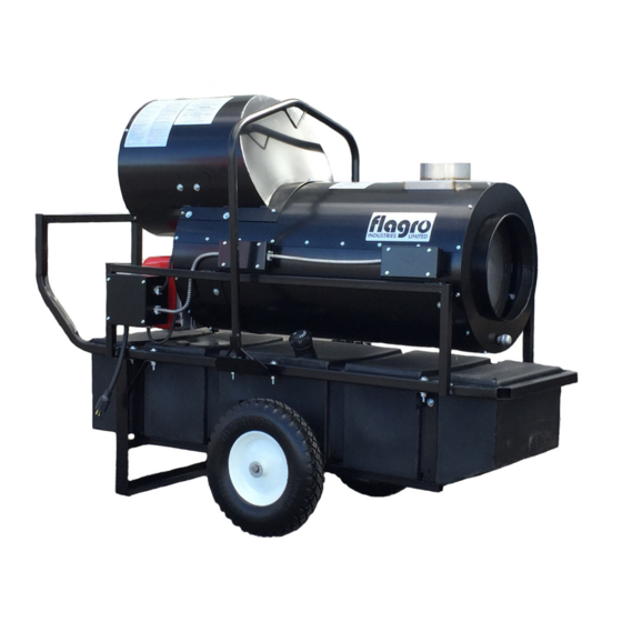
FVO-200RC42 INDIRECT FIRED SPACE HEATERS
CERTIFIED FOR USE IN CANADA AND U.S.A.
As per CSA B140.8 Portable Oil Fired Heaters / CSA B140.02003 Oil Burning Equipment
UL733 Oil fired heaters
Construction Heaters Unattended Type.
Issue date: July 1, 2017
2003325
FLAGRO INDUSTRIES LIMITED
ST. CATHARINES, ONTARIO
CANADA
- 1 -
Advertisement
Table of Contents

Related Manuals for Flagro FV-200RC Series


Summary of Contents for Flagro FV-200RC Series
- Page 1 CERTIFIED FOR USE IN CANADA AND U.S.A. As per CSA B140.8 Portable Oil Fired Heaters / CSA B140.02003 Oil Burning Equipment UL733 Oil fired heaters Construction Heaters Unattended Type. Issue date: July 1, 2017 2003325 FLAGRO INDUSTRIES LIMITED ST. CATHARINES, ONTARIO CANADA - 1 -...
- Page 2 GENERAL HAZARD WARNING: FAILURE TO COMPLY WITH THE PRECAUTIONS AND INSTRUCTIONS PROVIDED WITH THIS HEATER, CAN RESULT IN DEATH, SERIOUS BODILY INJURY AND PROPERTY LOSS OR DAMAGE FROM HAZARDS OF FIRE, EXPLOSION, BURN, ASPHYXIATION, CARBON MONOXIDE POISONING, AND/OR ELECTRICAL SHOCK. ONLY PERSONS UNDERSTAND...
- Page 3 This heater is designed and approved for use as a construction heater under CSA B140.8 Portable Oil Fired Heaters / CSA B140.02003 Oil Burning Equipment & UL733 Oil Fired heaters. We cannot anticipate every use which may be made of our heaters. CHECK WITH YOU LOCAL FIRE SAFETY AUTHORITY IF YOU HAVE QUESTIONS ABOUT APPLICATIONS.
-
Page 4: Installation
INSTALLATION: The installation of this heater for use with No.1, No.2, Diesel or Kerosene and shall conform with local codes or, in the absence of codes, with the National Fuel Gas Code ANSI Z223.1/NFPA 54. For recommended installation practices refer to CSA Standard B139. - Page 5 POWER SUPPLY INDICATOR LIGHT: The power supply indicator light will help detect any faulty power supplied to the heater such as; grounding issues, reverse polarity or missing/poor connections. Warning Light Indications Green Light ……………… Meets Power Requirements Solid Red Light………….. Reverse Polarity Solid Red &...
- Page 6 1. VERTICAL FLUE TERMINATIONS VERTICAL FLUE RUN HORIZONTAL FLUE RUN - RISE RATIO 1:10 FLUE OUTLET OF HEATER 2. HORIZONTAL FLUE TERMINATIONS FLUE OUTLET OF HEATER EXTERIOR WALL VENT TERMINATION MUST BE A MINIMUM OF 2FT HIGHER THAN ANY POINT WITHIN 10FT.
-
Page 7: Maintenance
OUTLET DUCTING: Hitex heater duct with a minimum temperature handling of 300 deg F including wire reinforcement to prevent collapsing. Heater is designed for use with 1 x 12” (FV-HD12) or 1 x 16” (FV-HDG16) diameter ducting equipped with pin lock or cuff &... -
Page 8: Start-Up Instructions
11. Heat Exchanger should be cleaned if smokey conditions continue even after the air adjustments on the burner are made. START UP INSTRUCTIONS: Position heater properly on a level surface. Be sure the toggle switch in is the “OFF” position. Ensure burner “air gate”... -
Page 9: To Shut Down
TO SHUT DOWN: Move toggle switch to “OFF” position. Do not disconnect power supply until the heat exchanger cools down NOTE: Fan will continue to operate after the burner shuts down. Once the unit cools down, the fan will stop. IF HEATER FAILS TO START: Press manual reset button at rear of burner. -
Page 10: Safe Operation Precautions
SAFE OPERATION PRECAUTIONS: Do not fill fuel tank while heater is operation. Do not attempt to start heater if excess oil remains in the heat exchanger. Use switch to shut down the heater. Do not try to shut down the heater by unplugging the electrical cord. - Page 11 (4) on the fan housing cover. Once set, the air adjustment plate should be secured in place by tightening SCREWS 2 and 3. C) The final position of the air adjustment plate will vary on each installation. Use instruments to establish the proper settings for maximum CO and a smoke reading of zero.
- Page 12 TEMPERATURE FEELER GAUGE ADJUSTMENT (ATTACHED TO FAN SWITCH) The temperature feeler gauge is required to be always touching the heater exchanger. The temperature feeler gauge controls the air flow over the fan switch, which eliminates any unnecessary fan cycling. The temperature feeler gauge can be adjusted for different outside temperatures, by rotating the location of the temperature feeler gauge holes.
- Page 13 WARNING: DO NOT activate burner until proper oil line connections have been made, or failure of the pump shaft seal may occur. - 13 -...
- Page 14 WARNING: If a neutral or ground lead is attached to this terminal, the CONTROL BOX on the burner will be damaged should lockout occur. - 14 -...
- Page 15 INSERTION / REMOVAL OF DRAWER ASSEMBLY To remove drawer assembly, loosen SCREW (3), then unplug CONTROL BOX (1) by carefully pulling it back and then up. Remove the AIR TUBE COVER PLATE (5) by loosening the two retaining SCREWS (4). Loosen SCREW (2), and then slide the complete drawer assembly out of the combustion head as shown.
-
Page 16: Electrode Setting
NOZZLE PLACEMENT Remove the NOZZLE ADAPTER (2) from the DRAWER ASSEMBLY by loosening the SCREW (1). Insert the proper NOZZLE into the NOZZLE ADAPTER and tighten securely (Do not over tighten). Replace adapter, with nozzle installed, into drawer assembly and secure with screw (1). -
Page 17: Oil Line Connections
TURBULATOR SETTING Loosen NUT (1), then turn SCREW (2) until the INDEX MARKER (3) is aligned with the correct index number as per the Burner Set-up chart, on page 12. Retighten the RETAINING NUT (1) Zero and five are scale indicators only. From left to right, the first line is NOTE: 5 and the last line 0. - Page 18 PARTS LIST FOR FVO-200RC42 Part Number Part Description FV-201 1/2 HP Fan Motor FV-202RC 14" BC Impeller FV-202RCA 14" BC Impeller Venturi FV-203 12" Wheel FV-204 12" Power Cord c/w Plug End FV-205 SS Heat Exchanger 40-113-D3.5GALV 1/2" X 3.5" Galvanized Nipple 40-108-8GALV 1/2"...
- Page 19 FVO-220 Clear Fuel Line 6" (Tank to Filter) FVO-221 Clear Fuel Line 7.5" (Filter to Burner) FVO-222 Clear Fuel Return Line (Burner to Tank) 48-6B Brass Fitting (Tank to inlet Fuel Line) 48-6C Brass Fitting (Inlet Side of Filter) 2103-C-CGA 3/8"...
- Page 21 RIELLO BURNER F5 - PARTS LIST DIAGRAM PART NUMBER DESCRIPTION FV-20136483-OIL PLASTIC BURNER COVER C/W LABELS FVO-3006993 RETURN LINE FVO-3006992 SUPPLY LINE FVO-C700-1029 IGNITION MODULE FVO-3002278 SUB-BASE FOR IGNITION MODULE FVO-3006553 COIL U-BRACKET C/W KNURLED NUT FVO-3002279 PUMP COIL FVO-20136488 BURNER PUMP FVO-3000443 PUMP DRIVE KEY...
- Page 22 FV-200RC SERIES - WIRING SCHEMATIC 2018 POWER INDICATOR FAN SWITCH 115 VAC FAN MOTOR SWITCH REMOTE THERMOSTAT REAR HIGH FRONT HIGH LIMIT SWITCH LIMIT SWITCH BURNER LIGHT FLAGRO INDUSTRIES LIMITED FV-200RC WS 2018 TITLE: FV-200RC - WIRING SCHEMATIC DWG. NO.