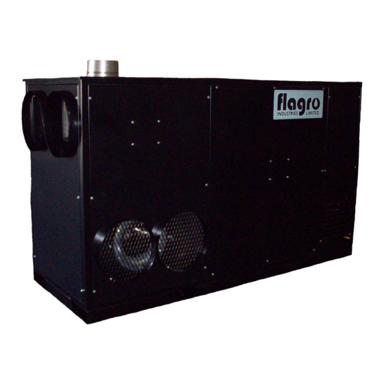
Flagro FVP-750 Operating Instructions Manual

Flagro FVP-750 Operating Instructions Manual

Indirect fired space heaters

Advertisement

OPERATING INSTRUCTIONS MANUAL
(Please retain for future reference)
For
FVN/P-750 INDIRECT FIRED SPACE HEATERS
FOR OUTDOOR AND INDOOR INSTALLATIONS
CERTIFIED FOR USE IN CANADA AND U.S.A.
As per Standard ANSI Z83.7/CSA 2.14 2011 Gas Fired Construction Heaters / Unattended Type.
Issue date July 1, 2012
FLAGRO INDUSTRIES LIMITED
ST. CATHARINES, ONTARIO
CANADA

Advertisement

Table of Contents
loading

Summary of Contents for Flagro FVP-750

  • Page 1 FVN/P-750 INDIRECT FIRED SPACE HEATERS FOR OUTDOOR AND INDOOR INSTALLATIONS CERTIFIED FOR USE IN CANADA AND U.S.A. As per Standard ANSI Z83.7/CSA 2.14 2011 Gas Fired Construction Heaters / Unattended Type. Issue date July 1, 2012 FLAGRO INDUSTRIES LIMITED ST. CATHARINES, ONTARIO CANADA...
  • Page 2 GENERAL HAZARD WARNING: FAILURE TO COMPLY WITH THE PRECAUTIONS AND INSTRUCTIONS PROVIDED WITH THIS HEATER, CAN RESULT IN DEATH, SERIOUS BODILY INJURY AND PROPERTY LOSS OR DAMAGE FROM HAZARDS OF FIRE, EXPLOSION, BURN, ASPHYXIATION, CARBON MONOXIDE POISONING, AND/OR ELECTRICAL SHOCK. ONLY PERSONS WHO CAN UNDERSTAND AND FOLLOW THE INSTRUCTIONS SHOULD USE OR SERVICE THIS HEATER.
  • Page 3: Specifications

    ABOUT APPLICATIONS. Other standards govern the use of fuel gases and heat producing products in specific applications. Your local authority can advise you about these. SPECIFICATIONS Model …………………………………………………….…. FVP-750 Propane FVN-750 Natural Gas Input …………………………………………………….…... 750,000 btuh Fuel …………………………………………………………. FVP-750 Propane FVN-750 Natural Gas Manifold Pressure ………………………………………….
  • Page 4: Installation

    INSTALLATION: The installation of this heater for use with natural gas shall conform with local codes or, in the absence of codes, with the National Fuel Gas Code ANSI Z233.1/NFPA 54 and the Natural Gas and Propane Installation Code, CSA B149.1.
  • Page 5 The gas must be turned off at the propane supply cylinder(s) when the heater is not in use. When the heater is to be stored indoors, the connection between the propane supply cylinder(s) and the heater must be disconnected and the cylinders removed from the heater and stored in accordance with Standard for the Storage and Handling or Liquefied Petroleum Gases, ANSI/NFPA 58 and CSA B149.1, Natural Gas and Propane Installation Code.
  • Page 6: Power Supply

    ELECTRICAL: This appliance is equipped with a grounded receptacle for your protection against shock hazard and should be plugged directly into a properly grounded plug. The electrical grounding of the heater shall be in compliance with the National Electrical Code, ANSI/NFPA 70, or CSA C22.1, Canadian Electrical Code, Part I. THIS APPLIANCE IS ABLE TO RECEIVE 1 PHASE OR 3 PHASE POWER.
  • Page 7 FLUE TERMINATIONS 90 DEG ELBOW 45 DEG ELBOW EXTERIOR WALL FLUE OUTLET OF HEATER A - Vertical vent run must be a minimum of 2ft from heater outlet. B - Maximum horizontal run is 20ft Note: 90deg Elbow = 5ft C - Vent termination in horizontal position must be minimum 2ft from wall.
  • Page 8: Maintenance

    MAINTENANCE: 1. Every construction heater should be inspected before each use, and at least annually by a qualified service person. Incorrect maintenance my result in improper operation of the heater and serious injury could occur. 2. Service and maintenance should only be done by a qualified service person. The hose assemblies shall be visually inspected prior to each use of the heater.
  • Page 9: To Shut Down

    Turn disconnect switch (single or three phase) depending on power supply to “ON” position Move fuel selector valve to correct position – LP or NG Move switch to “MANUAL” position for manual control. “OR” Move switch to “THERMOSTAT” position for thermostatic control. Please Note: 1.
  • Page 10: Safe Operation Precautions

    IF HEATER FAILS TO START: Press manual reset button at rear of burner. Check gas pressure supply. Supply and manifold pressure must follow those on rating plate. Ensure proper power supply is being used. If heater fails to ignite after 3 attempts, call your supplier for service. SAFE OPERATION PRECAUTIONS: For use with propane or natural gas only.
  • Page 11 COMBUSTION AIR ADJUSTMENTS: NOTE: Proper combustion air adjustment must be achieved using a certified combustion analyzer to ensure complete combustion. The air adjustment should be made to achieve 10% CO on natural gas and 12% CO on propane. SETTING THE AIR ADJUSTMENT PLATE A) Regulation of the combustion air flow is made by adjustment of the manual AIR ADJUSTMENT PLATE (1) after loosening the FIXING SCREWS (2 and 3).
  • Page 12: Burner Dimensions

    BURNER SET-UP CHART FIRING RATE HEAD AIR DAMPER (BTUH) SETTING SETTING 750,000 ***Please Note: FVN/P-750 is not equipped with the “servomotor”. BURNER DIMENSIONS - 12 -...
  • Page 13 ELECTRODE AND FLAME PROBE ADJUSTMENTS IMPORTANT: Do not turn the ignition electrode. Leave it as shown in the drawing. If the ignition electrode is put near the ionization probe, the amplifier of the control box may be damaged. - 13 -...
  • Page 14 - 14 -...
  • Page 15 ***Please note: FVN/P-750 is a single stage burner only. - 15 -...
  • Page 16 INPUT CONNECTIONS TRANSFORMER OFFERS 4 DIFFERENT INPUT POWER SUPPLY OPTIONS FACTORY SET AT 220V. IT IS IMPORTANT TO CHANGE YOUR INPUT CONNECTION BASED ON YOUR POWER SUPPLY, AS THE BURNER WILL NOT OPERATE PROPERLY...
  • Page 17: High Limit

    FV-750– PARTS LIST BOLT ON HINGE HIGH LIMIT REAR DOOR LATCH FV-706 – 250F FV-726 FV-725 FV-707 – 200F THERMOSTAT GREEN LIGHT RED LIGHT FV-414B S-1020C S-1020B 3 PHASE & 1 PHASE ON/OFF POWER SWITCH 3 POSITION SWITCH RECEPTACLE 3 PHASE & 1 PHASE FV-730 –...
  • Page 18: Power Relay

    FV-750 PARTS LIST 15 H.P. VFD 750V TRANSFORMER 3 PHASE/1 PHASE PLUG END FV-727 – 3 PHASE FV-703 FV-704 FV-728 – 1 PHASE 6AMP FUSE/2 POLE CLASS 15 AMP BREAKER POWER RELAY CC FUSE HOLDER FV-708 – 6 AMP FUSE FV-734 –...
  • Page 19: Ignition Control

    FV-750 PARTS LIST 7.5 H.P. FAN MOTOR BLOWER ASSEMBLY FV-701 FV-702 FV-750 BURNER PARTS LIST - OIL IGNITION CONTROL PHOTO CELL FUEL PUMP FV0-C700-1029 FV0-3002280 FV0-C7001011 FAN MOTOR ELECTRODE ASSEMBLY OIL NOZZLE FV-3005845 FV0-3005903 FV-733 ( 4.50 X 60W...
  • Page 20: Oil Filter

    COIL OIL FILTER BURNER COVER INSERT FVO-419 FVO-3002279 FVO-3007235 PART NUMBER A – 49-6D ELBOW B – FVO-735 FUEL SUPPLY TO TIGER LOOP C – FVO-738 FUEL RETURN LINE D – 49-6B ELBOW E – 49-6B ELBOW F – FVO-736 FUEL LINE, TIGER LOOP TO FILTER G –...
  • Page 21: Ignition Module

    FV-750 BURNER PARTS LIST – LP/NG ELECTRODE AIR PRESSURE SWITCH BURNER ORIFICE FVNP-3006962 FLAME ROD FVNP-3006703 FVNP-3020210 FVNP-3020321 IONIZATION LEAD BURNER COVER BURNER MOTOR FVNP-3007246 FV-3005845 FVNP-3007310 IGNITION MODULE ON/OFF VALVE GAS SELECTOR VALVE FVNP-3013072 2103-F-CGA 2103-E-CGA (1 “) (3/4”)
  • Page 22: Body Panels

    BODY PANELS DESCRIPTION FV750-840 FV750-824 RIGHT SIDE CENTRE PANEL FV750-823 LEFT SIDE CENTRE PANEL FV750-828 RIGHT SIDE FRONT PANEL FV750-827 LEFT SIDE FRONT PANEL - INLET FV750-835 LEFT SIDE REAR PANEL FV750-834 RIGHT SIDE REAR PANEL FV750-837 REAR ACCESS DOOR FV750-829 FRONT OUTLET PANEL...
  • Page 23 PARTS LIST FOR FVN/P-750 SERIES Part Number Part Description FV-701 7.5 HP PRIMARY FAN MOTOR FV-702 BLOWER ASSEMBLY FV-703 15 HP VFD FV-704 750VA TRANSFORMER FV-705 SS HEAT EXCHANGER FV-706 HIGH LIMIT (OUTLET) 250F FV-707 HIGH LIMIT (REAR) 200F FV-708 3.5 AMP CLASS CC FUSE (TWO PER HEATER) FV-709 2 POLE CLASS CC FUSE HOLDER...
  • Page 24 FV-728 1 PH 50AMP PLUG END FV-729 3 PH 30AMP RECEPTACLE FV-730 1 PH 50AMP RECEPTACLE FV-730A 1 PH 50AMP RECEPTACLE COVER FV-731 3 PH (ON/OFF) DISCONNECT BOX FV-732 1 PH (ON/OFF) DISCONNECT BOX FV-734 POWER RELAY - AS OF 2014 FVNP-739 1"...

This manual is also suitable for:

Fvn-750

Table of Contents