Table of Contents
Advertisement
Quick Links
OPERATING INSTRUCTIONS MANUAL
(Please retain for future reference)
For
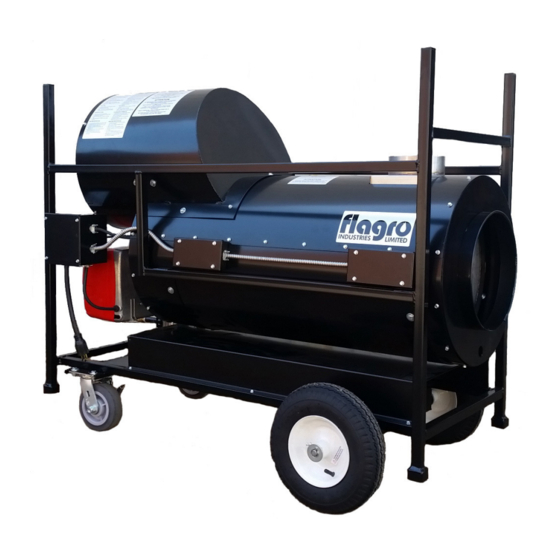
FVNP-200RC INDIRECT FIRED SPACE HEATERS
CERTIFIED FOR USE IN CANADA AND U.S.A.
As per Standard ANSI Z83.7/CSA 2.14 2000 Gas Fired Construction Heaters / Unattended Type.
Issue date:
2003325
FLAGRO INDUSTRIES LIMITED
ST. CATHARINES, ONTARIO
CANADA
Advertisement
Table of Contents

Related Manuals for Flagro FVNP-200RC


Summary of Contents for Flagro FVNP-200RC
- Page 1 OPERATING INSTRUCTIONS MANUAL (Please retain for future reference) FVNP-200RC INDIRECT FIRED SPACE HEATERS CERTIFIED FOR USE IN CANADA AND U.S.A. As per Standard ANSI Z83.7/CSA 2.14 2000 Gas Fired Construction Heaters / Unattended Type. Issue date: 2003325 FLAGRO INDUSTRIES LIMITED ST.
- Page 2 GENERAL HAZARD WARNING: FAILURE TO COMPLY WITH THE PRECAUTIONS AND INSTRUCTIONS PROVIDED WITH THIS HEATER, CAN RESULT IN DEATH, SERIOUS BODILY INJURY AND PROPERTY LOSS OR DAMAGE FROM HAZARDS OF FIRE, EXPLOSION, BURN, ASPHYXIATION, CARBON MONOXIDE POISONING, AND/OR ELECTRICAL SHOCK. ONLY PERSONS WHO CAN UNDERSTAND AND FOLLOW THE INSTRUCTIONS SHOULD USE OR SERVICE THIS HEATER.
- Page 3 ABOUT APPLICATIONS. Other standards govern the use of fuel gases and heat producing products in specific applications. Your local authority can advise you about these. SPECIFICATIONS Model …………………………………………………….…. FVNP-200RC Input Range…………………………………….…... …….. 200,000 btuh Fuel …………………………………………………………. Propane Natural Gas Manifold Pressure ………………………………………….
-
Page 4: Installation
INSTALLATION: The installation of this heater for use with natural gas shall conform with local codes or, in the absence of codes, with the National Fuel Gas Code ANSI Z223.1/NFPA 54 and the Natural Gas and Propane Installation Code, CSA B149.1-00. This heater must be installed by a qualified gas technician, following local codes published by the authority having jurisdiction. - Page 5 CONNECTING THE CYLINDER: If cylinders are being use, no cylinders smaller than 100lb capacity shall be used. These cylinders must supply a vapour withdrawal only. All cylinder connections must be made using a wrench to tighten the POL fitting. Be sure that the cylinder valve is in the closed position when connection or disconnecting the cylinder.
- Page 6 FUEL: This heater is a dual fuel unit and operates on propane & natural gas. The manifold pressures are listed on the approval label. You do not need to change any of the burner components; you however need to make sure the fuel selector valve on the manifold is in the proper fuel position.
- Page 7 FLUE PIPE: For outdoor applications the flue pipe connection must terminate with a vertical run at least 2 ft long with a rain cap. For indoor installations the venting must consist of a minimum 2 ft vertical run to a maximum of 20 ft total vent length. See diagram below for horizontal vent installation.
- Page 8 VENT TERMINATION IN HORIZONTAL POSITION MUST BE MINIMUM 4ft FROM ANY COMBUSTABLE SURFACE EXTERIOR VERTICAL VENT TERMINATION MUST BE A MINIMUM OF 2ft. NOTE: ALL VENT TERMINATIONS MUST HAVE A RAIN CAP INSTALLED AS PER LOCAL CODE REQUIREMENTS. OUTLET DUCTING: Hitex heater duct with a minimum temperature handling of 300 deg F including wire reinforcement to prevent collapsing.
-
Page 9: Start-Up Instructions
START UP INSTRUCTIONS: Position heater properly on a level surface. Be sure the toggle switch is in the ‘OFF” position. Connect the fuel supplier to heater (leak test all connections) Refer to chart #1 for hose sizing. Ensure the fuel selector valve is in the proper position. (LP or NG) Ensure burner “air gate”... -
Page 10: To Shut Down
TO SHUT DOWN: Close main gas supply valve while heater is operating. Move toggle switch to “OFF” position. The main fan will run until the heater exchanger cools down. Do not disconnect power supply until the heat exchanger cools down. Disconnect fuel supply from heater. - Page 11 COMBUSTION AIR ADJUSTMENTS: NOTE: Proper combustion air adjustment must be achieved using a certified combustion analyzer to ensure complete combustion. The air adjustment should be made to achieve 10% CO on natural gas and 12% CO on propane. SETTING THE AIR ADJUSTMENT PLATE A) Regulation of the combustion air flow is made by adjustment of the manual AIR ADJUSTMENT PLATE (1) after loosening the FIXING SCREWS (2 and 3).
- Page 12 TEMPERATURE FEELER GAUGE ADJUSTMENT (ATTACHED TO FAN SWITCH) The temperature feeler gauge is required to be always touching the heater exchanger. The temperature feeler gauge controls the air flow over the fan switch, which eliminates any unnecessary fan cycling. The temperature feeler gauge can be adjusted for different outside temperatures, by rotating the location of the temperature feeler gauge holes.
- Page 13 Model 200 Inches 9 3/16 10 11/16 6 11/16 11 5/8 3 15/16 3 9/16 *G1 is for LBT version Gasket thickness is 4 millimeters - 13 -...
-
Page 14: Typical Gas Train Layout
ELECTRODE AND FLAME PROBE ADJUSTMENTS IMPORTANT: Do not turn the ignition electrode. Leave it as shown in the drawing. If the ignition electrode is put near the ionization probe, the amplifier of the control box may be damaged. TYPICAL GAS TRAIN LAYOUT FIELD SUPPLIED RIELLO SUPPLIED GAS TRAIN LEGEND... - Page 15 - 15 -...
Need help?
Do you have a question about the FVNP-200RC and is the answer not in the manual?
Questions and answers