Table of Contents
Advertisement
Quick Links
OPERATING INSTRUCTIONS MANUAL
(Please retain for future reference)
For
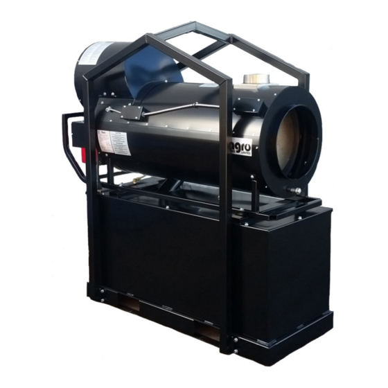
FVO-400RCBT INDIRECT FIRED SPACE HEATERS
BULK TANK
CERTIFIED FOR USE IN CANADA AND U.S.A.
As per CSA B140.8 Portable Oil Fired Heaters / CSA B140.02003 Oil Burning Equipment
Construction Heaters Unattended Type.
UL 733 Oil-fired Air Heaters
Issue date: September 9, 2016
2003325
FLAGRO INDUSTRIES LIMITED
ST. CATHARINES, ONTARIO
CANADA
- 1 -
Advertisement
Table of Contents

Related Manuals for Flagro FVO-400RCBT


Summary of Contents for Flagro FVO-400RCBT
- Page 1 OPERATING INSTRUCTIONS MANUAL (Please retain for future reference) FVO-400RCBT INDIRECT FIRED SPACE HEATERS BULK TANK CERTIFIED FOR USE IN CANADA AND U.S.A. As per CSA B140.8 Portable Oil Fired Heaters / CSA B140.02003 Oil Burning Equipment Construction Heaters Unattended Type.
- Page 2 GENERAL HAZARD WARNING: FAILURE TO COMPLY WITH THE PRECAUTIONS AND INSTRUCTIONS PROVIDED WITH THIS HEATER, CAN RESULT IN DEATH, SERIOUS BODILY INJURY AND PROPERTY LOSS OR DAMAGE FROM HAZARDS OF FIRE, EXPLOSION, BURN, ASPHYXIATION, CARBON MONOXIDE POISONING, AND/OR ELECTRICAL SHOCK. ONLY PERSONS UNDERSTAND...
-
Page 3: Specifications
This heater is designed and approved for use as a construction heater under CSA B140.8 Portable Oil Fired Heaters / CSA B140.02003 Oil Burning Equipment. We cannot anticipate every use which may be made of our heaters. CHECK WITH YOU LOCAL FIRE SAFETY AUTHORITY IF YOU HAVE QUESTIONS ABOUT APPLICATIONS. -
Page 4: Installation
INSTALLATION: The installation of this heater for use with No.1, No.2, Diesel or Kerosene and shall conform with local codes or, in the absence of codes, with the National Fuel Gas Code ANSI Z223.1/NFPA 54. Installation of the unit shall be in accordance with the regulations of the authorities having jurisdiction or the CSA Standard B139. - Page 5 FV SERIES CONSTRUCTION HEATER – VENTING REQUIREMENTS 1. VERTICAL FLUE TERMINATIONS VERTICAL FLUE RUN HORIZONTAL FLUE RUN - RISE RATIO 1:10 FLUE OUTLET OF HEATER 2. HORIZONTAL FLUE TERMINATIONS FLUE OUTLET OF HEATER EXTERIOR WALL THIS HEATER IS CONSIDERED A CATEGORY 3 APPLIANCE (SPECIAL VENTING SYSTEM) STACK TEMPERATURES CAN BE UP TO 900 DEG F.
-
Page 6: Maintenance
OUTLET DUCTING: Heater duct with a minimum temperature handling of 300 deg F. including wire reinforcement to prevent collapsing. Heater is designed for use with 12” diameter or 16”” ducts equipped with pin lock couplings or cuff & buckle. Install ducting to outlet on the heater using pin-locks or cuff &... -
Page 7: Start-Up Instructions
9. The High Limit Switches (Part# FV-406 & FV-437) should be checked each season. These limit switches will ensure the burner shuts down if the temperature exceeds 150º F at rear of unit and 250º F at the outlet. 10. Fuel tank should be drained on a regular basis by removing drain plug. CAUTION: Do not have any source of ignition near the heater when draining tank. -
Page 8: To Shut Down
TO SHUT DOWN: Move Burner switch to “OFF” position & move Pre-Heater switch to “OFF” position. NOTE: Fan will continue to operate after the burner shuts down. Once the unit cools down, the fan will stop. IF HEATER FAILS TO START: Press manual reset button at rear of burner. -
Page 9: Safe Operation Precautions
SAFE OPERATION PRECAUTIONS: Do not fill fuel tank while heater is operation. Do not attempt to start heater if excess oil remains in the heat exchanger. Use switch to shut down the heater. Do not try to shut down the heater by unplugging the electrical cord. - Page 10 SETTING THE AIR ADJUSTMENT PLATE Regulation combustion air flow is made by adjustment of the manual AIR ADJUSTMENT PLATE (1) after loosening the FIXING SCREWS (2 & 3). The initial setting of the air adjustment plate should made according to Column 5 in the Burner Set-up Chart.
- Page 11 * Note – Air damper setting is typically set at 4 for operation in colder temperatures. A combustion analyzer should always be used when setting the burner. TEMPERATURE FEELER GAUGE ADJUSTMENT (ATTACHED TO FAN SWITCH) The temperature feeler gauge is required to be always touching the heater exchanger.
- Page 12 POWER SUPPLY INDICATOR LIGHT/VOLT METER/PRE- HEATER: The power supply indicator light will help detect any faulty power supplied to the heater such as; grounding issues, reverse polarity or missing/poor connections. Warning Light Indications Green Light ……………… Meets Power Requirements Solid Red Light………….. Reverse Polarity Solid Red &...
-
Page 13: Electrical Connections
ELECTRICAL CONNECTIONS It is advisable to leave the control box off the sub-base while completing the electrical connections to the burner. The burner may be controlled using either a DIRECT LINE VOLTAGE control circuit (120V AC 60 cycle) OR a LOW VOLTAGE control (24V AC 60 cycle) using a R8038A Honeywell switching relay or equivalent. - Page 14 APPLICATION FIELD WIRING REMOTE SENSING OF SAFETY LOCKOUT: The SAFETY SWITCH in the 530SE CONTROL BOX is equipped with a contact allowing remote sensing of burner lockout. The electrical connection is made at terminal 4 (●) on the SUB- BASE. Should lockout occur the 530SE CONTROL BOX will supply a power source of 120Vac to the connection terminal.
- Page 15 INSERTION / REMOVAL OF DRAWER ASSEMBLY To remove drawer assembly, loosen SCREW (3), then unplug CONTROL BOX (1) by carefully pulling it back and then up. Remove the AIR TUBE COVER PLATE (5) by loosening the two retaining SCREWS (4). Loosen SCREW (2), and then slide the complete drawer assembly out of the combustion head as shown.
-
Page 16: Electrode Setting
NOZZLE PLACEMENT Remove the NOZZLE ADAPTER (2) from the DRAWER ASSEMBLY by loosening the SCREW (1). Insert the proper NOZZLE into the NOZZLE ADAPTER and tighten securely (Do not over tighten). Replace adapter, with nozzle installed, into drawer assembly and secure with screw (1). -
Page 17: Oil Line Connections
TURBULATOR SETTING Loosen NUT (1), then turn SCREW (2) until the INDEX MARKER (3) is aligned with the correct index number as per the Burner Set-up chart, on page 12. Retighten the RETAINING NUT (1) NOTE: Zero and five are scale indicators only. From left to right, the first line is 5 and the last line 0. - Page 19 RIELLO BURNER F10 - PARTS LIST DIAGRAM PART NUMBER DESCRIPTION FV-20136636-OIL PLASTIC BURNER COVER C/W LABELS FVO-3006992 SUPPLY LINE FVO-3006993 RETURN LINE FVO-3020076 PUMP ADAPTER FOR NOZZLE HOLDER FUEL LINE FVO-C700-1029 IGNITION MODULE FVO-3002278 SUB-BASE FOR IGNITION MODULE FVO-3006553 COIL U-BRACKET C/W KNURLED NUT FVO-3002279 PUMP COIL FVO-20136488...
- Page 20 PARTS LIST FOR FVO-400RCBT Part Number Part Description FV-401A 1 HP FAN MOTOR FOR FVO/FVN/FVP (RC UNIT) FV-402RC 16" BC IMPELLER FOR FV-400RC FV-402RCA VENTURI FOR 16" BC IMPELLER FV-404 18" POWER CORD C/W PLUG END FV-405 SS HEAT EXCHANGER 40-113-D7GALV 1/2"...
- Page 21 OIL FUEL LINE 16 1/4" (BULK TANK TO FILTER) FVO-420BT FVO-421BT OIL FUEL LINE 15 3/4" (FILTER TO BURNER) FVO-422BT OIL FUEL LINE 10 3/4" (BURNER TO BULK TANK) FVO-BTH TANK HARNESS FOR FVO-BT 48-6C BRASS FITTING (POLY TANK TO FILTER) 122-CB 3/8 X 1/4 REDUCING HEX NIPPLE 49-6C...
- Page 22 FV-400RC WIRING DIAGRAM 150F High Limit Thermostat Connection Riello Burner Manual 250F Remote High Limit Toggle 1 HP 1725 RPM Burner Motor Lockout Fan Limit Relay "4" "8" Power Supply Indicator RELAY CONNECTIONS: "8" - HARTLAND RELAY 120 Volt 120 Volt "4"...
Need help?
Do you have a question about the FVO-400RCBT and is the answer not in the manual?
Questions and answers