Table of Contents
Advertisement
Quick Links
OPERATING INSTRUCTIONS MANUAL
(Please retain for future reference)
For
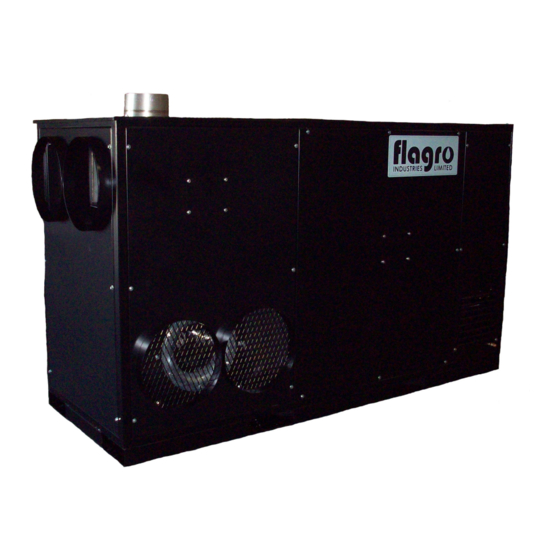
FVO-750 INDIRECT FIRED SPACE HEATERS
CERTIFIED FOR USE IN CANADA AND U.S.A.
As per CSA B140.8 Portable Oil Fired Heaters / CSA B140.02003 Oil Burning Equipment
Construction Heaters Unattended Type.
Issue date July 1, 2012
FLAGRO INDUSTRIES LIMITED
ST. CATHARINES, ONTARIO
CANADA
- 1 -
Advertisement
Table of Contents

Subscribe to Our Youtube Channel
Related Manuals for Flagro FVO-750 Series


Summary of Contents for Flagro FVO-750 Series
- Page 1 CERTIFIED FOR USE IN CANADA AND U.S.A. As per CSA B140.8 Portable Oil Fired Heaters / CSA B140.02003 Oil Burning Equipment Construction Heaters Unattended Type. Issue date July 1, 2012 FLAGRO INDUSTRIES LIMITED ST. CATHARINES, ONTARIO CANADA - 1 -...
- Page 2 GENERAL HAZARD WARNING: FAILURE TO COMPLY WITH THE PRECAUTIONS AND INSTRUCTIONS PROVIDED WITH THIS HEATER, CAN RESULT IN DEATH, SERIOUS BODILY INJURY AND PROPERTY LOSS OR DAMAGE FROM HAZARDS OF FIRE, EXPLOSION, BURN, ASPHYXIATION, CARBON MONOXIDE POISONING, AND/OR ELECTRICAL SHOCK. ONLY PERSONS UNDERSTAND...
-
Page 3: Specifications
This heater is designed and approved for use as a construction heater under CSA B140.8 Portable Oil Fired Heaters / CSA B140.02003 Oil Burning Equipment. We cannot anticipate every use which may be made of our heaters. CHECK WITH YOU LOCAL FIRE SAFETY AUTHORITY IF YOU HAVE QUESTIONS ABOUT APPLICATIONS. -
Page 4: Installation
INSTALLATION: The installation of this heater for use with No.1, No.2, Diesel or Kerosene and shall conform with local codes or, in the absence of codes, with the National Fuel Gas Code ANSI Z223.1/NFPA 54. Installation of the unit shall be in accordance with the regulations of the authorities having jurisdiction or the CSA Standard B139. - Page 5 INPUT CONNECTIONS TRANSFORMER OFFERS 4 DIFFERENT INPUT POWER SUPPLY OPTIONS FACTORY SET AT 220V. IT IS IMPORTANT TO CHANGE YOUR INPUT CONNECTION BASED ON YOUR POWER SUPPLY, AS THE BURNER WILL NOT OPERATE PROPERLY - 5 -...
- Page 6 FLUE PIPE: For outdoor applications the flue pipe connection must terminate with a vertical run of at least 2ft complete with rain cap. For indoor installations the venting must consist of a minimum 2ft vertical run to a maximum of 20ft total vent length. See diagram below for horizontal vent installation.
-
Page 7: Maintenance
DUCTING: Heater duct with a minimum temperature rating of 300 deg F including wire reinforcement to prevent collapsing. Heater is designed for use with 2 x 16” diameter ducts equipped with gear clamp couplings (FV-HDG16). Install ducting to the heater outlet using gear clamps provided on the collar of the ducting. -
Page 8: Start-Up Instructions
START UP INSTRUCTIONS: Position heater properly & on a level surface before operating Connect Fuel supply to heater Ensure the (Thermostat / Manual) selector switch is in the “OFF” position Attach power supply, 208-230V/1-phase or 208-230V/3-phase to appropriate receptacle. Turn disconnect switch (Single or Three phase) depending on power supply to “ON”... -
Page 9: To Shut Down
TO SHUT DOWN: Close main fuel supply valve Move Thermostat/Manual switch to “OFF” position. Waiting until blower fan shuts down (3 minutes approx.) Turn Disconnect switch (single phase or three phase) depending on power supply to “OFF” position. Turn main power breaker to “OFF” position Disconnect heater from fuel supply. -
Page 10: Safe Operation Precautions
SAFE OPERATION PRECAUTIONS: Do not fill external fuel tank while heater is in operation. Do not attempt to start heater if excess oil remains in the heat exchanger. Use selector switch to shut down the heater. Do not try to shut down the heater by unplugging the electrical cord. Note: DAMAGE TO THE HEATER WILL OCCUR Do not plug anything other than the thermostat into the “Thermostat”... - Page 11 COMBUSTION AIR ADJUSTMENTS: NOTE: Proper combustion air adjustment must be achieved using a certified combustion analyzer and smoke tester to ensure complete combustion. The air adjustment should be made to achieve 10% CO and No. 1 or “trace” smoke. (Bacharach Scale) AIR SHUTTER SETTING LOW FIRE SETTING Loosen PRESSURE RELEASING SCREW (1).
- Page 12 F) Retighten PRESSURE RELEASE SCREW (1). Note: The low fire pressure regulator is pre-set at the factory to 100 PSI (7 bar). To vary or regulate this pressure it is necessary to attach a pressure gauge to the PRESSURE PORT (6). Loosen the PRESSURE RELEASE SCREW (1) as in step A above.
- Page 13 BURNER SET-UP CHART ACTUAL NOZZLE PUMP FIRING RATE TURBULATOR SIZE PRESSURE DAMPER ± 5% SETTING SETTING 5.42 4.50 x 60° W * Note – Air damper setting is typically set at 5 for operation in colder temperatures. A combustion analyzer should always be used when setting the burner.
-
Page 14: Electrical Connections
ELECTRICAL CONNECTIONS It is advisable to leave the control box off the sub-base while completing the electrical connections to the burner. Using the appropriate diagram below, make electrical connections to the burner. All wiring must be done in accordance with existing electrical codes, both national and local. - Page 15 REMOTE SENSING OF SAFETY LOCKOUT: The SAFETY SWITCH in the 530SE CONTROL BOX is equipped with a contact allowing remote sensing of burner lockout. The electrical connection is made at terminal 4 ( ) on the SUB- BASE. Should lockout occur the 530SE CONTROL BOX will supply a power source of 120Vac to the connection terminal.
- Page 16 INSERTION / REMOVAL OF DRAWER ASSEMBLY To remove drawer assembly, loosen SCREW (3), then unplug CONTROL BOX (1) by carefully pulling it back and then up. Remove the AIR TUBE COVER PLATE (5) by loosening the two retaining SCREWS (4). Loosen SCREW (2), and then slide the complete drawer assembly out of the combustion head as shown.
-
Page 17: Electrode Setting
NOZZLE PLACEMENT Remove the NOZZLE ADAPTER (2) from the DRAWER ASSEMBLY by loosening the SCREW (1). Insert the proper NOZZLE into the NOZZLE ADAPTER and tighten securely (Do not over tighten). Replace adapter, with nozzle installed, into drawer assembly and secure with screw (1). -
Page 18: Oil Line Connections
TURBULATOR SETTING Loosen NUT (1), then turn SCREW (2) until the INDEX MARKER (3) is aligned with the correct index number as per the Burner Set-up chart, on page 12. Retighten the RETAINING NUT (1) NOTE: Zero and five are scale indicators only. From left to right, the first line is 5 and the last line 0. -
Page 19: High Limit
FV-750– PARTS LIST BOLT ON HINGE HIGH LIMIT REAR DOOR LATCH FV-706 – 250F FV-726 FV-725 FV-707 – 200F THERMOSTAT GREEN LIGHT RED LIGHT FV-414B S-1020C S-1020B 3 PHASE & 1 PHASE ON/OFF POWER SWITCH 3 POSITION SWITCH RECEPTACLE 3 PHASE & 1 PHASE FV-730 –... -
Page 20: Power Relay
FV-750 PARTS LIST 15 H.P. VFD 750V TRANSFORMER 3 PHASE/1 PHASE PLUG END FV-703 FV-727 – 3 PHASE FV-704 FV-728 – 1 PHASE 15 AMP BREAKER 6AMP FUSE/2 POLE CLASS POWER RELAY CC FUSE HOLDER FV-708 – 6 AMP FUSE FV-734 –... -
Page 21: Ignition Control
FV-750 PARTS LIST 7.5 H.P. FAN MOTOR BLOWER ASSEMBLY FV-701 FV-702 FV-750 BURNER PARTS LIST - OIL IGNITION CONTROL PHOTO CELL FUEL PUMP FV0-C700-1029 FV0-20132573 FVO-20062453 FAN MOTOR ELECTRODE ASSEMBLY OIL NOZZLE FV-3005845 FV0-3005903 FV-733 ( 4.50 X 60W... - Page 22 TIGER LOOP COIL BURNER COVER SYSTEM FV-20137281- OIL FVO-3002279 FVO-TLSF DIESEL FILTER SYSTEM A – FVO-735 FUEL SUPPLY TO TIGER LOOP B – FVO-738 FUEL RETURN LINE C – 48-6C BRASS FITTING D – 49-6C ELBOW E – FVO-737 FUEL LINE, FILTER TO BURNER F –...
- Page 23 FV-750 BURNER PARTS LIST – LP/NG ELECTRODE AIR PRESSURE SWITCH BURNER ORIFICE FVNP-3006962 FLAME ROD FVNP-3006703 FVNP-3020210 FVNP-3020321 IONIZATION LEAD BURNER COVER BURNER MOTOR FV-3005845 FV-20137281-LPNG FVNP-3007310 IGNITION MODULE ON/OFF VALVE GAS SELECTOR VALVE FVNP-3013072 2103-F-CGA 2103-E-CGA (1 “) (3/4”)
-
Page 24: Body Panels
BODY PANELS DESCRIPTION FV750-840 FV750-824 RIGHT SIDE CENTRE PANEL FV750-823 LEFT SIDE CENTRE PANEL FV750-828 RIGHT SIDE FRONT PANEL FV750-827 LEFT SIDE FRONT PANEL - INLET FV750-835 LEFT SIDE REAR PANEL FV750-834 RIGHT SIDE REAR PANEL FV750-837 REAR ACCESS DOOR FV750-829 FRONT OUTLET PANEL... - Page 25 F-20 OIL FIRED BURNER - PARTS DIAGRAM...
- Page 27 RIELLO BURNER F20 - PARTS LIST DIAGRAM PART NUMBER DESCRIPTION FV-20137281-OIL PLASTIC BURNER BACK COVER C/W LABELS FVO-3007028 O - RING FVO-3007583 REGULATOR FVO-3005847 CONNECTOR FVO-3006571 CONNECTOR FVO-20137291 PIPE CONNECTOR FVO-3002278 BLEEDER SCREW FVO-3006553 COIL U-BRACKET AND KNURLED NUT FVO-3002280 PUMP COIL FVO-3007806 PUMP...
- Page 28 PARTS LIST FOR FVO-750 SERIES Part Number Part Description FV-701 7.5 HP PRIMARY FAN MOTOR FV-702 BLOWER ASSEMBLY FV-703 15 HP VFD FV-704 750VA TRANSFORMER FV-705 SS HEAT EXCHANGER FV-706 HIGH LIMIT (OUTLET) 250F FV-707 HIGH LIMIT (REAR) 200F FV-708 3.5 AMP CLASS CC FUSE (TWO PER HEATER)
- Page 29 FV-725 REAR DOOR LATCH (INCLUDES MOUNTS & RAILS) FV-726 DOOR HINGE (TWO PER HEATER) FV-727 3 PH 30AMP PLUG END FV-728 1 PH 50AMP PLUG END FV-729 3 PH 30AMP RECEPTACLE (COVER INCLUDED) FV-730 1 PH 50AMP RECEPTACLE FV-730A 1 PH 50AMP RECEPTACLE COVER FV-731 3 PH (ON/OFF) DISCONNECT BOX FV-732...
Need help?
Do you have a question about the FVO-750 Series and is the answer not in the manual?
Questions and answers