Advertisement
OPERATING INSTRUCTIONS MANUAL
(Please retain for future reference)
For
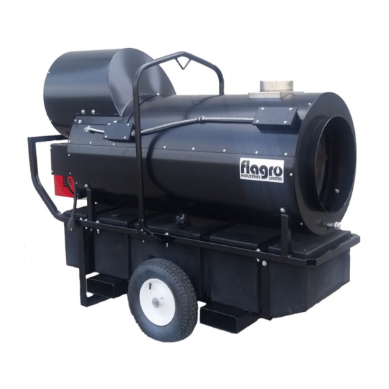
FVO-400RC INDIRECT FIRED SPACE HEATERS
CERTIFIED FOR USE IN CANADA AND U.S.A.
As per CSA B140.8 Portable Oil Fired Heaters / CSA B140.02003 Oil Burning Equipment
Construction Heaters Unattended Type/ UL 733 Oil-fired Air Heaters
Issue date: September 9, 2016
2003325
FLAGRO INDUSTRIES LIMITED
ST. CATHARINES, ONTARIO
CANADA
- 1 -
Advertisement
Table of Contents

Related Manuals for Flagro FVO-400RC


Summary of Contents for Flagro FVO-400RC
- Page 1 OPERATING INSTRUCTIONS MANUAL (Please retain for future reference) FVO-400RC INDIRECT FIRED SPACE HEATERS CERTIFIED FOR USE IN CANADA AND U.S.A. As per CSA B140.8 Portable Oil Fired Heaters / CSA B140.02003 Oil Burning Equipment Construction Heaters Unattended Type/ UL 733 Oil-fired Air Heaters...
- Page 2 GENERAL HAZARD WARNING: FAILURE TO COMPLY WITH THE PRECAUTIONS AND INSTRUCTIONS PROVIDED WITH THIS HEATER, CAN RESULT IN DEATH, SERIOUS BODILY INJURY AND PROPERTY LOSS OR DAMAGE FROM HAZARDS OF FIRE, EXPLOSION, BURN, ASPHYXIATION, CARBON MONOXIDE POISONING, AND/OR ELECTRICAL SHOCK. ONLY PERSONS UNDERSTAND...
- Page 3 ABOUT APPLICATIONS. Other standards govern the use of fuel gases and heat producing products in specific applications. Your local authority can advise you about these. SPECIFICATIONS Model …………………………………………………….…. FVO-400RC Input …………………………………………………….…... Range 325,000 – 390,000 Fuel …………………………………………………………. No.1, No. 2,...
- Page 4 –10º C (8º F). REMOTE TANK OPTION: The FVO-400RC may be installed with a remote fuel tank providing the manufacturer approved FVO-TLS remote fuel kit is used. This kit includes the tiger loop system using a single line supply and pressure relief valve. This system prevents overpressure fuel supply and stops the fuel flow in the case of a leak in the fuel line where pump vacuum pressure is lost.
- Page 5 FLUE PIPE: Flue pipe connection must terminate with a vertical run at least 2ft long. The vent outlet on the heater is 6” diameter. Certified venting must be used at all times. Vent cap should be installed in situations where downdrafts occur. All venting must correspond with the CSA B149 standard or in its absence, local codes.
- Page 6 VENT TERMINATION IN HORIZONTAL POSITION MUST BE MINIMUM 4ft FROM ANY COMBUSTABLE SURFACE EXTERIOR VERTICAL VENT TERMINATION MUST BE A MINIMUM OF 2ft. NOTE: ALL VENT TERMINATIONS MUST HAVE A RAIN CAP INSTALLED AS PER LOCAL CODE REQUIREMENTS. OUTLET DUCTING: Hitex heater duct with a minimum temperature handling of 300 deg F.
-
Page 7: Start-Up Instructions
6. Change fuel filter insert (Part# FVO-419) once per month. Change fuel filter cartridge (Part# FVO-418) once every 6 months. 7. Change oil nozzle once per year. FV-435B (2.00 X 60B/W), FV-435WC (1.75 X 60B/W) 8. Fan Limit Switch (Part# FV-407A) should be replaced if the fan motor does not shut off after the heat exchanger has cooled down. -
Page 8: To Shut Down
Please Note: 1. If using Thermostat on unit, unit must be started in Thermostat position. 2 When changing between manual and thermostat operation, the heater must be left in the “OFF” position for 30 seconds to prevent the burner from locking out. - Page 9 SAFE OPERATION PRECAUTIONS: Do not fill fuel tank while heater is operation. Do not attempt to start heater if excess oil remains in the heat exchanger. Use switch to shut down the heater. Do not try to shut down the heater by unplugging the electrical cord.
- Page 10 according to Column 5 in the Burner Set-up Chart. B) The proper number on the manual AIR ADJUSTMENT PLATE (1) should line up with the SETTING INDICATOR (4) on the fan housing cover. Once set, the air adjustment plate should be secured in place by tightening SCREWS 2 and 3.
- Page 11 Turn the temperature feeler gauge so that the holes are parallel with the heat exchanger. This will help the fan switch to remain cool and not overheat. See following: If supply air is cold (under -5ºC): Turn the temperature feeler gauge so that the holes are closed off as the air goes over the heat exchanger.
- Page 12 POWER SUPPLY INDICATOR LIGHT/VOLT METER/PRE-HEATER: The power supply indicator light will help detect any faulty power supplied to the heater such as; grounding issues, reverse polarity or missing/poor connections. Warning Light Indications Green Light ……………… Meets Power Requirements Solid Red Light………….. Reverse Polarity Solid Red &...
-
Page 13: Electrical Connections
ELECTRICAL CONNECTIONS It is advisable to leave the control box off the sub-base while completing the electrical connections to the burner. The burner may be controlled using either a DIRECT LINE VOLTAGE control circuit (120V AC 60 cycle) OR a LOW VOLTAGE control (24V AC 60 cycle) using a R8038A Honeywell switching relay or equivalent. - Page 14 APPLICATION FIELD WIRING REMOTE SENSING OF SAFETY LOCKOUT: The SAFETY SWITCH in the 530SE CONTROL BOX is equipped with a contact allowing remote sensing of burner lockout. The electrical connection is made at terminal 4 ( ) on the SUB- BASE.
- Page 15 INSERTION / REMOVAL OF DRAWER ASSEMBLY To remove drawer assembly, loosen SCREW (3), then unplug CONTROL BOX (1) by carefully pulling it back and then up. Remove the AIR TUBE COVER PLATE (5) by loosening the two retaining SCREWS (4). Loosen SCREW (2), and then slide the complete drawer assembly out of the combustion head as shown.
-
Page 16: Electrode Setting
NOZZLE PLACEMENT Remove the NOZZLE ADAPTER (2) from the DRAWER ASSEMBLY by loosening the SCREW (1). Insert the proper NOZZLE into the NOZZLE ADAPTER and tighten securely (Do not over tighten). Replace adapter, with nozzle installed, into drawer assembly and secure with screw (1). -
Page 17: Oil Line Connections
TURBULATOR SETTING Loosen NUT (1), then turn SCREW (2) until the INDEX MARKER (3) is aligned with the correct index number as per the Burner Set-up chart, on page 12. Retighten the RETAINING NUT (1) Zero and five are scale indicators only. From left to right, the first line is NOTE: 5 and the last line 0. - Page 18 PARTS LIST FOR FVO-400RC Part Number Part Description FV-401A 1 HP FAN MOTOR FOR FVO/FVN/FVP (RC UNIT) FV-402RC 16" BC IMPELLER FOR FV-400RC FV-402RCA VENTURI FOR 16" BC IMPELLER FV-403A 16" WHEEL - FLAT FREE FV-404 18" POWER CORD C/W PLUG END...
- Page 19 FVO-418 FUEL FILTER (COMPLETE) FVO-419 FUEL FILTER (INSERT ONLY) FVO-420A CLEAR FUEL LINE 14" (TANK TO FILTER) FVO-421A CLEAR FUEL LINE 6.5" (FILTER TO BURNER) FVO-422A CLEAR FUEL LINE 14" (BURNER TO TANK) 48-6C BRASS FITTING (POLY TANK TO FILTER) 2103-C-CGA 3/8"...
- Page 20 FVO-3006553 COIL U-BRACKET C/W KNURLED NUT FVO-20136491 CONNECTION FOR THE NOZZLE HOLDER FVO-20136639 NOZZLE HOLDER FVO-3006966 ELECTRODE SUPPORT FVO-3006978 TURBULATOR DISC. FVO-3006983 END CONE ADAPTER (F10 BURNER) FVO-3006992 PIPE CONNECTOR - SUPPLY FVO-3006993 PIPE CONNECTOR - RETURN FVO-3007077 CRUSHABLE METAL WASHER FVO-3007087 NOZZLE OUTLET WASHER FOR F10 BURNER FVO-3007203...
- Page 21 FV-400RC WIRING DIAGRAM 150F High Limit Thermostat Connection Riello Burner Manual 250F Remote High Limit Toggle 1 HP 1725 RPM Burner Motor Lockout Fan Limit Omron Relay Power Supply Indicator 120 Volt 120 Volt Meter Meter Line Neutral...
Need help?
Do you have a question about the FVO-400RC and is the answer not in the manual?
Questions and answers