Table of Contents
Advertisement
Quick Links
OPERATING INSTRUCTIONS MANUAL
(Please retain for future reference)
For
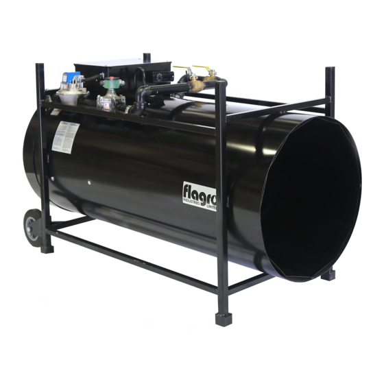
F-1500T DUAL FUEL CONSTRUCTION HEATER
CERTIFIED FOR USE IN CANADA AND U.S.A.
As per Standard ANSI Z83.7 2000/
CSA 2.14 2000 Gas Fired Construction Heaters Unvented/Unattended Type.
FLAGRO INDUSTRIES LIMITED
ST. CATHARNIES, ONTARIO
CANADA
Advertisement
Table of Contents

Related Manuals for Flagro F-1500T


Summary of Contents for Flagro F-1500T
- Page 1 OPERATING INSTRUCTIONS MANUAL (Please retain for future reference) F-1500T DUAL FUEL CONSTRUCTION HEATER CERTIFIED FOR USE IN CANADA AND U.S.A. As per Standard ANSI Z83.7 2000/ CSA 2.14 2000 Gas Fired Construction Heaters Unvented/Unattended Type. FLAGRO INDUSTRIES LIMITED ST. CATHARNIES, ONTARIO...
- Page 2 GENERAL HAZARD WARNING: FAILURE TO COMPLY WITH THE PRECAUTIONS AND INSTRUCTIONS PROVIDED WITH THIS HEATER, CAN RESULT IN DEATH, SERIOUS BODILY INJURY AND PROPERTY LOSS OR DAMAGE FROM HAZARDS OF FIRE, EXPLOSION, BURN, ASPHYXIATION, CARBON MONOXIDE POISONING, AND/OR ELECTRICAL SHOCK. ONLY PERSONS WHO CAN UNDERSTAND AND FOLLOW THE INSTRUCTIONS SHOULD USE OR SERVICE THIS HEATER.
- Page 3 ABOUT APPLICATIONS. Other standards govern the use of fuel gases and heat producing products in specific applications. Your local authority can advise you about these. SPECIFICATIONS Model Number F-1500T Input 650,000 to 1,500,000 btuh Fuel Natural Gas or Propane Inlet Pressure Natural Gas: 9.0”...
- Page 4 This heater must be located at least 10ft (3m) from any propane gas cylinder. This heater shall not be directed toward any propane gas container within 20ft (6m). CLEARANCE TO COMBUSTIBLES: F-1500T TOP: 4 ft FRONT: 22 ft SIDES: 2 ft...
- Page 5 PRESSURES: MAXIMUM INLET PRESSURES: LP: 14.0 IN. WC. NG: 14.0 IN. WC. MINIMUM INLET PRESSURES: LP: 11.0 IN. WC. NG: 9.0 IN. WC. This heater must be supplied by pressures indicated on the approval label. Over pressure may cause controls to fail. DO NOT supply this unit with more than ½...
- Page 6 MAINTENANCE: Every construction heater should be inspected before each use, and at least annually by a qualified service person. The hose assembly shall be visually inspected prior to each use of the heater. If it is evident there is excessive abrasion or wear, or the hose is cut, it must be replaced prior to the heater being put into operation.
- Page 7 F-1500T START UP INSTRUCTIONS: 1. Set fuel selector valve according to gas supply to be used 2. Connect construction heater to gas supply with approved hose assembly. 3. Plug the electrical cord into a 20 amp supply. 4. Open all gas supply valves.
- Page 8 F-1500T TROUBLESHOOTING ANALYSIS: PROBLEM: HEATER WILL NOT LIGHT Air switch improperly set. POSSIBLE CAUSE: Use centre adjusting screw to set REMEDY: air switch. Turn clockwise to increase sensitivity, turn counter clockwise to decrease sensitivity. Blockage in copper inlet tubes. POSSIBLE CAUSE: Disconnect tubes from air switch.
- Page 9 Faulty Solenoid. POSSIBLE CAUSE: Ensure solenoid is energized. REMEDY: (use volt meter) Ensure plunger in the solenoid is being activated. (use manometer at test point after solenoid) (use volt meter) Incorrect Gas Supply. POSSIBLE CAUSE: Ensure required gas supply pressures REMEDY: are supplied to the heater.
- Page 10 PROBLEM: HEATER WILL NOT REMAIN LIT AFTER START UP Faulty flamerod wire. POSSIBLE CAUSE: Check flamerod wire for any damage. REMEDY: Ensure connections are secure. Replace flamerod if necessary.
- Page 11 F-1500T Parts List...
- Page 12 F-1500T Parts List VALVE TRAIN...
- Page 13 F-1500T Parts List...
- Page 14 F-1500T Parts List Item # Description 1 1/4" X 3 1/2" Nipple 40-113G3.5 1 1/4" BM Union 40-104-20 1 1/4" X 90 BM Street Elbow 40-116-20 1 1/4" X 5 1/2" Nipple 40-113G5.5 Fuel Shut Off Valve S-1003A Fuel Selector Valve S-1003 1 1/4"...
- Page 15 F-1500T WIRING DIAGRAM 2010 CLEAR LIGHT ON/OFF HIGH LIMIT RELAY 120 VOLT FAN MOTOR RED LIGHT GROUND MOMENTARY ON COIL THERMOSTAT AIR SWITCH FLAME ROD GROUND GREEN LIGHT SPARK PLUG BLUE BLACK ORANGE FENWAL IGNITION BOARD (POTTED CONTROL) MODULATING GAS VALVE...
- Page 16 PARTS LIST FOR F-1500T Part Number Part Description S-1000 1 HP MOTOR S-1001 FAN BLADE S-1502 MODULATING REGULATOR VALVE S-1002FS S.S. FILTER SCREEN S-1003 FUEL SELECTOR VALVE S-1003A FUEL SHUT OFF VALVE S-1004 SOLENOID VALVE S-1505 BURNER S-406 FLAME ROD...
Need help?
Do you have a question about the F-1500T and is the answer not in the manual?
Questions and answers