Flagro FVO-400 Operating Instructions Manual
Indirect fired space heaters
Hide thumbs
Also See for FVO-400:
- Operating instructions manual (26 pages) ,
- Operating instructions manual (21 pages)
Advertisement
OPERATING INSTRUCTIONS MANUAL
(Please retain for future reference)
For
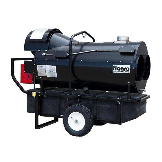
FVO-400 INDIRECT FIRED SPACE HEATERS
CERTIFIED FOR USE IN CANADA AND U.S.A.
As per CSA B140.8 Portable Oil Fired Heaters / CSA B140.02003 Oil Burning Equipment
Construction Heaters Unattended Type.
UL 733 Oil-fired Air Heaters
Issue date October 1, 2015
2003325
FLAGRO INDUSTRIES LIMITED
ST. CATHARINES, ONTARIO
CANADA
- 1 -
Advertisement
Table of Contents

Related Manuals for Flagro FVO-400


Summary of Contents for Flagro FVO-400
- Page 1 OPERATING INSTRUCTIONS MANUAL (Please retain for future reference) FVO-400 INDIRECT FIRED SPACE HEATERS CERTIFIED FOR USE IN CANADA AND U.S.A. As per CSA B140.8 Portable Oil Fired Heaters / CSA B140.02003 Oil Burning Equipment Construction Heaters Unattended Type. UL 733 Oil-fired Air Heaters...
- Page 2 GENERAL HAZARD WARNING: FAILURE TO COMPLY WITH THE PRECAUTIONS AND INSTRUCTIONS PROVIDED WITH THIS HEATER, CAN RESULT IN DEATH, SERIOUS BODILY INJURY AND PROPERTY LOSS OR DAMAGE FROM HAZARDS OF FIRE, EXPLOSION, BURN, ASPHYXIATION, CARBON MONOXIDE POISONING, AND/OR ELECTRICAL SHOCK. ONLY PERSONS WHO CAN UNDERSTAND AND FOLLOW THE INSTRUCTIONS SHOULD USE OR SERVICE THIS HEATER.
-
Page 3: Specifications
SPECIFICATIONS Model …………………………………………………….…. FVO-400 Input …………………………………………………….…... Range 325,000 – 390,000 Fuel …………………………………………………………. No.1, No. 2, diesel or kerosene Fuel Pressure ……………………………………………..170 psi Nozzle ………………………………………………………. 2.25 x 45B 390,000 Btu 2.00 x 60B/W 353,000 BTU 1.75 x 60B/W 325,000 BTU Ignition ………………………………………………………. -
Page 4: Installation
–10º C (8º F). REMOTE TANK OPTION: The FVO-400 may be installed with a remote fuel tank providing the manufacturer approved FVO-TLS remote fuel kit is used. This kit includes the tiger loop filter system using a single line supply and pressure relief valve (FVO-TLPRV) This system prevents overpressure fuel supply and stops the fuel flow in the case of a leak in the fuel line where pump vacuum pressure is lost. - Page 5 FLUE PIPE: For outdoor applications, a minimum of 2 FT flue pipe with rain cap is recommended but not required to be connected to the flue on the heat exchanger. The vent outlet on the heater is 6” diameter. Certified venting must be used at all times.
-
Page 6: Maintenance
VENT TERMINATION MUST BE A MINIMUM OF 2FT HIGHER THAN ANY POINT WITHIN 10FT. MAXIMUM HORIZONTAL RUN IS 30FT. NOTE: 90deg ELBOW = 10ft HORIZONTAL VENT ALLOWANCE 45deg ELBOW = 5ft HORIZONTAL VENT ALLOWANCE VENT TERMINATION IN HORIZONTAL POSITION MUST BE MINIMUM 4ft FROM ANY COMBUSTABLE SURFACE EXTERIOR VERTICAL VENT TERMINATION MUST BE A MINIMUM OF 2ft. -
Page 7: Start-Up Instructions
8. Fan Limit Switch (Part# FV-407A) should be replaced if the fan motor does not shut off after the heat exchanger has cooled down. 9. The High Limit Switches (Part# FV-406 & FV-437) should be checked each season. These limit switches will ensure the burner shuts down if the temperature exceeds 150º... -
Page 8: To Shut Down
4. In the event that a Generator is being used and the generator runs out of fuel, make sure the heater switch is in the “OFF” position before restarting generator, failure to do so may damage heater. TO SHUT DOWN: Move Burner switch to “OFF”... -
Page 9: Safe Operation Precautions
SAFE OPERATION PRECAUTIONS: Do not fill fuel tank while heater is operation. Do not attempt to start heater if excess oil remains in the heat exchanger. Use switch to shut down the heater. Do not try to shut down the heater by unplugging the electrical cord. - Page 10 B) The proper number on the manual AIR ADJUSTMENT PLATE (1) should line up with the SETTING INDICATOR (4) on the fan housing cover. Once set, the air adjustment plate should be secured in place by tightening SCREWS 2 and 3. C) The final position of the air adjustment plate will vary on each installation.
- Page 11 If supply air is cold (under -5ºC): Turn the temperature feeler gauge so that the holes are closed off as the air goes over the heat exchanger. This will reduce fan cycling and the unit from shutting down. See following: In extreme cold conditions, cover the holes on the temperature feeler gauge using foil tape.
-
Page 12: Electrical Connections
ELECTRICAL CONNECTIONS It is advisable to leave the control box off the sub-base while completing the electrical connections to the burner. The burner may be controlled using either a DIRECT LINE VOLTAGE control circuit (120V AC 60 cycle) OR a LOW VOLTAGE control (24V AC 60 cycle) using a R8038A Honeywell switching relay or equivalent. - Page 13 APPLICATION FIELD WIRING REMOTE SENSING OF SAFETY LOCKOUT: The SAFETY SWITCH in the 530SE CONTROL BOX is equipped with a contact allowing remote sensing of burner lockout. The electrical connection is made at terminal 4 (●) on the SUB- BASE. Should lockout occur the 530SE CONTROL BOX will supply a power source of 120Vac to the connection terminal.
- Page 14 INSERTION / REMOVAL OF DRAWER ASSEMBLY To remove drawer assembly, loosen SCREW (3), then unplug CONTROL BOX (1) by carefully pulling it back and then up. Remove the AIR TUBE COVER PLATE (5) by loosening the two retaining SCREWS (4). Loosen SCREW (2), and then slide the complete drawer assembly out of the combustion head as shown.
-
Page 15: Electrode Setting
NOZZLE PLACEMENT Remove the NOZZLE ADAPTER (2) from the DRAWER ASSEMBLY by loosening the SCREW (1). Insert the proper NOZZLE into the NOZZLE ADAPTER and tighten securely (Do not over tighten). Replace adapter, with nozzle installed, into drawer assembly and secure with screw (1). -
Page 16: Oil Line Connections
TURBULATOR SETTING Loosen NUT (1), then turn SCREW (2) until the INDEX MARKER (3) is aligned with the correct index number as per the Burner Set-up chart, on page 12. Retighten the RETAINING NUT (1) NOTE: Zero and five are scale indicators only. From left to right, the first line is 5 and the last line 0. - Page 17 PARTS DIAGRAM – FVO-400 FV-408 FV-438 FV-P01 FV-P06 FV-434CB12 FVO-FR FV-405 40-113-D7 GALV & 40-108-8GALV FVO-416A FV-436A FV-403A FV-P02 FVO-416H FV-402 FV-406 FV-401 FV-P11 FV-P05 FV-P10 FVO-417B FVO-415 BURNER FV-407A FV-P08 FV-437 FV-404 FV-448 FVO-416G - 17 -...
- Page 18 FV-446 / FV-447 HC5-64 FV-431 FV-450SI FV-411 FV-409 FV-414B FVO-418 2103-C-CGA FVO-421A FVO-420A FVO-422A FVO-423A FVO-423B FV-437 FV-433 FV-407A FV-407G FV-433B - 18 -...
- Page 19 F-10 OIL FIRED BURNER - PARTS DIAGRAM...
- Page 20 RIELLO BURNER F10 - PARTS LIST DIAGRAM PART NUMBER DESCRIPTION FV-20136636-OIL PLASTIC BURNER COVER C/W LABELS FVO-3006992 SUPPLY LINE FVO-3006993 RETURN LINE FVO-3020076 PUMP ADAPTER FOR NOZZLE HOLDER FUEL LINE FVO-C700-1029 IGNITION MODULE FVO-3002278 SUB-BASE FOR IGNITION MODULE FVO-3006553 COIL U-BRACKET C/W KNURLED NUT FVO-3002279 PUMP COIL FVO-20136488...
- Page 21 PARTS PRICE LIST FOR FVO-400 Part Number Part Description FV-401 PRIMARY FAN MOTOR FV-402 16" FAN BLADE FV-403A 16" WHEEL - FLAT FREE 3.80KG FV-404 18" POWER CORD C/W PLUG END FV-405 SS HEAT EXCHANGER 40-113-D7GALV 1/2" X 7" GALVANIZED NIPPLE 40-108-8GALV 1/2"...
- Page 22 FVO-416H 42 US GALLON OIL TANK HARNESS (POLY TANK) FVO-417B OIL TANK CAP (POLY TANK) 40-121-6GALV OIL TANK DRAIN PLUG (FOR POLY TANK) FVO-418 FUEL FILTER (COMPLETE) FUEL FILTER (INSERT ONLY) FVO-419 FVO-420A CLEAR FUEL LINE - TANK TO FILTER FVO-421A CLEAR FUEL LINE - FILTER TO BURNER FVO-422A...
- Page 23 ACCESSORIES FV-HD12 12" X 12-FT HITEX DUCTING PIN LOCK FV-HD12X25 12" X 25-FT HITEX DUCTING PIN LOCK FV-HDG16 16" X 25-FT HITEX DUCTING CUFF & BUCKLE FV-THB THERMOSTAT C/W 25FT CORD/MALE PLUG END FV-THB (15M) THERMOSTAT C/W 50FT CORD/MALE PLUG END FVO-TLS TIGERLOOP SYSTEM C/W FILTER FVO-TLSF...
- Page 24 FV SERIES WIRING DIAGRAM FAN MOTOR "4" "8" RELAY BURNER BLUE FAN LIMIT RED LIGHT 250F HIGH LIMIT 150F HIGH LIMIT RELAY CONNECTION THERM TOGGLE "8" - HARTLAND RELAY "4" - OMRON RELAY FV-400 WIRING DIAGRAM - 2020...
Need help?
Do you have a question about the FVO-400 and is the answer not in the manual?
Questions and answers