Flagro FVO-400 Operating Instructions Manual
Indirect fired space heaters
Hide thumbs
Also See for FVO-400:
- Operating instructions manual (21 pages) ,
- Operating instructions manual (25 pages)
Advertisement
OPERATING INSTRUCTIONS MANUAL
(Please retain for future reference)
For
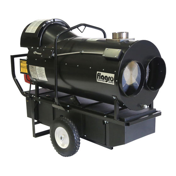
FVO-400 INDIRECT FIRED SPACE HEATERS
CERTIFIED FOR USE IN CANADA AND U.S.A.
As per CSA B140.8 Portable Oil Fired Heaters / CSA B140.02003 Oil Burning Equipment
Construction Heaters Unattended Type.
Issue date October 1, 2008
FLAGRO INDUSTRIES LIMITED
ST. CATHARINES, ONTARIO
CANADA
- 1 -
Advertisement
Table of Contents

Related Manuals for Flagro FVO-400


Summary of Contents for Flagro FVO-400
- Page 1 OPERATING INSTRUCTIONS MANUAL (Please retain for future reference) FVO-400 INDIRECT FIRED SPACE HEATERS CERTIFIED FOR USE IN CANADA AND U.S.A. As per CSA B140.8 Portable Oil Fired Heaters / CSA B140.02003 Oil Burning Equipment Construction Heaters Unattended Type. Issue date October 1, 2008 FLAGRO INDUSTRIES LIMITED ST.
- Page 2 GENERAL HAZARD WARNING: FAILURE TO COMPLY WITH THE PRECAUTIONS AND INSTRUCTIONS PROVIDED WITH THIS HEATER, CAN RESULT IN DEATH, SERIOUS BODILY INJURY AND PROPERTY LOSS OR DAMAGE FROM HAZARDS OF FIRE, EXPLOSION, BURN, ASPHYXIATION, CARBON MONOXIDE POISONING, AND/OR ELECTRICAL SHOCK. ONLY PERSONS UNDERSTAND...
-
Page 3: Specifications
ABOUT APPLICATIONS. Other standards govern the use of fuel gases and heat producing products in specific applications. Your local authority can advise you about these. SPECIFICATIONS Model …………………………………………………….…. FVO-400 Input …………………………………………………….…... 390,000 btuh Fuel …………………………………………………………. No.1, No. 2, diesel or kerosene Fuel Pressure …………………………………………….. -
Page 4: Installation
INSTALLATION: The installation of this heater for use with No.1, No.2, Diesel or Kerosene and shall conform with local codes or, in the absence of codes, with the National Fuel Gas Code ANSI Z223.1/NFPA 54. Installation of the unit shall be in accordance with the regulations of the authorities having jurisdiction or the CSA Standard B139. - Page 5 FV SERIES CONSTRUCTION HEATER – VENTING REQUIREMENTS 1. VERTICAL FLUE TERMINATIONS VERTICAL FLUE RUN HORIZONTAL FLUE RUN - RISE RATIO 1:10 FLUE OUTLET OF HEATER 2. HORIZONTAL FLUE TERMINATIONS FLUE OUTLET OF HEATER EXTERIOR WALL VENT TERMINATION MUST BE A MINIMUM OF 2FT HIGHER THAN ANY POINT WITHIN 10FT.
-
Page 6: Maintenance
DUCTING: Canvas heater duct with a minimum temperature handling of 300 deg F. including wire reinforcement to prevent collapsing. Heater is designed for use with 2 x 12” diameter ducts equipped with pin lock couplings (FV-D12). Install ducting to outlet on the heater using pin-locks provided on collar of ducting. -
Page 7: Start-Up Instructions
NOTE: No.1 fuel oil or kerosene is recommended for temperatures below -10º C / 8º F 11. Heat Exchanger should be cleaned if smokey conditions continue even after the air adjustments on the burner are made. START UP INSTRUCTIONS: Be sure the switch in is the “OFF” position. Ensure electrical cord is grounded and heater is on a level surface. -
Page 8: Safe Operation Precautions
IF HEATER FAILS TO START: Press manual reset button at rear of burner. Check fuel level. There must be 2-4 gallons of fuel in the tank for the heater to start properly. Make sure there are no air locks in fuel lines or filter. Ensure proper power supply and extension cord is being used. - Page 9 COMBUSTION AIR ADJUSTMENTS: NOTE: Proper combustion air adjustment must be achieved using a certified combustion analyzer and smoke tester to ensure complete combustion. The air adjustment should be made to achieve 10% CO and No. 1 or “trace” smoke. (Bacharach Scale) SETTING THE AIR ADJUSTMENT PLATE Regulation combustion air flow is made...
- Page 10 BURNER SET-UP CHART ACTUAL NOZZLE FIRING RATE PUMP PRESSURE TURBULATOR SIZE DAMPER ± 5% SETTING SETTING 2.75 2.25 x 45° 4 - 6 * Note – Air damper setting is typically set at 4 for operation in colder temperatures. A combustion analyzer should always be used when setting the the burner.
- Page 11 In extreme cold conditions, cover the holes on the temperature feeler gauge using foil tape. Ensure that the temperature feeler gauge is readjusted for warmer weather conditions. Failure to do so may result in burning out fan switches- not covered under warranty. - 11 -...
-
Page 12: Electrical Connections
ELECTRICAL CONNECTIONS It is advisable to leave the control box off the sub-base while completing the electrical connections to the burner. The burner may be controlled using either a DIRECT LINE VOLTAGE control circuit (120V AC 60 cycle) OR a LOW VOLTAGE control (24V AC 60 cycle) using a R8038A Honeywell switching relay or equivalent. - Page 13 APPLICATION FIELD WIRING REMOTE SENSING OF SAFETY LOCKOUT: The SAFETY SWITCH in the 530SE CONTROL BOX is equipped with a contact allowing remote sensing of burner lockout. The electrical connection is made at terminal 4 ( ) on the SUB- BASE.
- Page 14 INSERTION / REMOVAL OF DRAWER ASSEMBLY To remove drawer assembly, loosen SCREW (3), then unplug CONTROL BOX (1) by carefully pulling it back and then up. Remove the AIR TUBE COVER PLATE (5) by loosening the two retaining SCREWS (4). Loosen SCREW (2), and then slide the complete drawer assembly out of the combustion head as shown.
-
Page 15: Electrode Setting
NOZZLE PLACEMENT Remove the NOZZLE ADAPTER (2) from the DRAWER ASSEMBLY by loosening the SCREW (1). Insert the proper NOZZLE into the NOZZLE ADAPTER and tighten securely (Do not over tighten). Replace adapter, with nozzle installed, into drawer assembly and secure with screw (1). -
Page 16: Oil Line Connections
TURBULATOR SETTING Loosen NUT (1), then turn SCREW (2) until the INDEX MARKER (3) is aligned with the correct index number as per the Burner Set-up chart, on page 12. Retighten the RETAINING NUT (1) NOTE: Zero and five are scale indicators only. From left to right, the first line is 5 and the last line 0. - Page 17 Indirect Fired Heater FVO-400 Parts List...
- Page 18 Indirect Fired Heater FVO-400 Parts List Front Oil Filter Rear Limit Switch Box Fan Limit Switch accessories...
- Page 19 Indirect Fired Heater FVO-400 Parts List Control Box Front Limit Switch Box Fan and Motor Inside Control Box...
- Page 20 Indirect Fired Heater FVO-400 Parts List Accessories Item # Description Fan Motor Canopy FV-408 Lifting Harness FV-438 High Limit Box (Single Hole) FV-P11 48 US Gallon Oil Tank FVO-416 16 " Wheel FV-403 Oil Tank Cap FVO-417 Fan Limit Box (Double Hole)
- Page 21 POWER SUPPLY INDICATOR LIGHT - FVO-400 & FVNP-400 & FVO-200 & FVNP-200 * The power supply indicator light will help you detect any faulty power supplied to the heater. Control Box * The power supply indicator light will detect various power supply issues such as;...
- Page 22 FV-400 SERIES - WIRING SCHEMATIC 2011 POWER INDICATOR 115 VAC FAN MOTOR FAN SWITCH SWITCH REMOTE THERMOSTAT REAR HIGH FRONT HIGH LIMIT SWITCH LIMIT SWITCH BURNER LIGHT FLAGRO INDUSTRIES LIMITED TITLE: FVO-400 - WIRING SCHEMATIC DWG. NO. FV-400 WS 2011...
- Page 23 PARTS LIST FOR FVO-400 Part Number Part Description FV-401 PRIMARY FAN MOTOR FV-402 16" FAN BLADE FV-403 16" WHEEL FV-404 18" POWER CORD C/W PLUG END FV-405 SS HEAT EXCHANGER 40-113-D7GALV 1/2" X 7" GALVANIZED NIPPLE 40-108-8GALV 1/2" GALVANIZED CAP...
- Page 24 FVO-422 OIL FUEL RETURN LINE 10.5" (BURNER TO TANK) - YELLOW FVO-420A CLEAR FUEL LINE 14" (TANK TO FILTER) FVO-421A CLEAR FUEL LINE 6.5" (FILTER TO BURNER) FVO-422A CLEAR FUEL LINE 14" (BURNER TO TANK) 48-6C BRASS FITTING (POLY TANK TO FILTER) 2103-C-CGA 3/8"...
- Page 25 FVO-3005855 MOUNTING FLANGE FVO-3005869 ELECTRODE PORCELAIN FVO-3005891 ELECTRODE ASSEMBLY FVO-3006553 COIL U-BRACKET C/W KNURLED NUT FVO-3006965 NOZZLE ADAPTER FVO-3006966 ELECTRODE SUPPORT FVO-3006978 TURBULATOR DISC. FVO-3006980 NOZZLE OIL TUBE 10" FVO-3006992 PIPE CONNECTOR - SUPPLY FVO-3006993 PIPE CONNECTOR - RETURN FVO-3007223 CHASSIS FRONT PLATE FVO-3007234 BURNER BACK COVER...
Need help?
Do you have a question about the FVO-400 and is the answer not in the manual?
Questions and answers