Advertisement
Advertisement
Table of Contents

Subscribe to Our Youtube Channel
Related Manuals for Flagro FVNP-400


Summary of Contents for Flagro FVNP-400
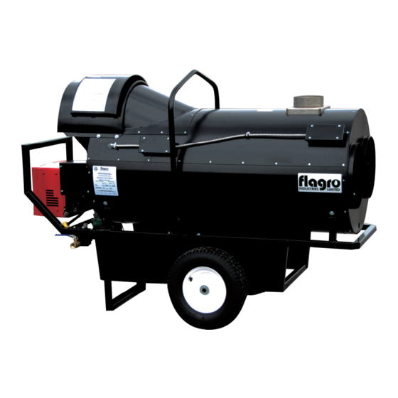
- Page 1 OPERATING INSTRUCTIONS MANUAL (Please retain for future reference) FVNP-400 INDIRECT FIRED SPACE HEATERS CERTIFIED FOR USE IN CANADA AND U.S.A. As per Standard ANSI Z83.7/CSA 21.4 2000 Gas Fired Construction Heaters / Unattended Type. FLAGRO INDUSTRIES LIMITED ST. CATHARINES, ONTARIO...
- Page 2 GENERAL HAZARD WARNING: FAILURE TO COMPLY WITH THE PRECAUTIONS AND INSTRUCTIONS PROVIDED WITH THIS HEATER, CAN RESULT IN DEATH, SERIOUS BODILY INJURY AND PROPERTY LOSS OR DAMAGE FROM HAZARDS OF FIRE, EXPLOSION, BURN, ASPHYXIATION, CARBON MONOXIDE POISONING, AND/OR ELECTRICAL SHOCK. ONLY PERSONS WHO CAN UNDERSTAND AND FOLLOW THE INSTRUCTIONS SHOULD USE OR SERVICE THIS HEATER.
-
Page 3: Specifications
ABOUT APPLICATIONS. Other standards govern the use of fuel gases and heat producing products in specific applications. Your local authority can advise you about these. SPECIFICATIONS Model …………………………………………………….…. FVNP-400 Input …………………………………………………….…... 390,000 btuh Fuel …………………………………………………………. Propane / Natural Gas Manifold Pressure …………………………………………. -
Page 4: Connecting The Cylinder
The installation of this heater for use with natural gas shall conform with local codes or, in the absence of codes, with the National Fuel Gas Code ANSI Z233.1/NFPA 54 and the Natural Gas and Propane Installation Code, CSA B149.1-00. This heater must be installed by a qualified gas technician, following local codes published by the authority having jurisdiction. - Page 5 PIPING: This heater must be installed by a qualified gas technician following local codes published by the authority having jurisdiction. Sizing of supply piping must be determined using the length of pipe run as well as total btuh rating of the appliance(s). Appropriate piping tables must be used to determine size of supply piping dependant on the length of run from source.
- Page 6 ELECTRICAL: WARNING Electrical Grounding Instructions This appliance is equipped with a three-prong (grounding) plug for your protection against shock hazard and should be plugged directly into a properly grounded three-prong receptacle. 115v supply must be available. Please note that the heater requires 15 amps for proper operation.
- Page 7 CLEARANCE TO COMBUSTIBLES: FRONT SIDES REAR FLUE PIPE 3 ft 10 ft 3 ft 3 ft 3 ft DUCTING: Hitex heater duct with a minimum temperature handling of 300 deg F. including wire reinforcement to prevent collapsing. Heater is designed for use with 2 x 12” diameter ducts equipped with pin lock couplings (FV-HD12).
- Page 8 FV SERIES CONSTRUCTION HEATER – VENTING REQUIREMENTS 1. VERTICAL FLUE TERMINATIONS VERTICAL FLUE RUN HORIZONTAL FLUE RUN - RISE RATIO 1:10 FLUE OUTLET OF HEATER 2. HORIZONTAL FLUE TERMINATIONS FLUE OUTLET OF HEATER EXTERIOR WALL VENT TERMINATION MUST BE A MINIMUM OF 2FT HIGHER THAN ANY POINT WITHIN 10FT.
-
Page 9: Maintenance
MAINTENANCE: 1. Every construction heater should be inspected before each use, and at least annually by a qualified service person. Incorrect maintenance my result in improper operation of the heater and serious injury could occur. 2. Service and maintenance should only be done by a qualified service person. The hose assemblies shall be visually inspected prior to each use of the heater. -
Page 10: Start-Up Instructions
START UP INSTRUCTIONS: Be sure the switch is in the “OFF” position. Ensure electrical cord is grounded and heater is on a level surface. Plug in supply cord to 115v, 15amp outlet. Move switch to “MANUAL” position for manual control. Move switch to “THERMOSTAT”... -
Page 11: Safe Operation Precautions
IF HEATER FAILS TO START: Press manual reset button at rear of burner. Check gas pressure supply. Supply and manifold pressure must follow those on rating plate. Ensure proper power supply and extension cord is being used. If heater fails to ignite after 3 attempts, call your supplier for service. SAFE OPERATION PRECAUTIONS: For use with propane or natural gas only. -
Page 12: Firing Rate
COMBUSTION AIR ADJUSTMENTS: NOTE: Proper combustion air adjustment must be achieved using a certified combustion analyzer to ensure complete combustion. The air adjustment should be made to achieve 10% CO on natural gas and 12% CO on propane. SETTING THE AIR ADJUSTMENT PLATE A) Regulation of the combustion air flow is made by adjustment of the manual AIR ADJUSTMENT PLATE (1) after loosening the FIXING SCREWS (2 and 3). - Page 13 TEMPERATURE FEELER GAUGE ADJUSTMENT (ATTACHED TO FAN SWITCH) The temperature feeler gauge is required to be always touching the heater exchanger. The temperature feeler gauge controls the air flow over the fan switch, which eliminates any unnecessary fan cycling. The temperature feeler gauge can be adjusted for different outside temperatures, by rotating the location of the temperature feeler gauge holes.
-
Page 14: Burner Dimensions
In extreme cold conditions, cover the holes on the temperature feeler gauge using foil tape. Ensure that the temperature feeler gauge is readjusted for warmer weather conditions. Failure to do so may result in burning out fan switches – not covered under warranty. PRINCIPAL BURNER COMPONENTS 1. - Page 15 Model 400 inches 10 5/16 1 3/8 13 11/16 3 3/4 4 1/8 2262 *G1 is for LBT version Gasket thickness is 4 millimeters ELECTRODE AND FLAME PROBE ADJUSTMENTS IMPORTANT: Do not turn the ignition electrode. Leave it as shown in the drawing.
-
Page 16: Field Wiring Diagram
GAS TRAIN LEGEND GAS SUPPLY & FLOW DIRECTION GAS APPLIANCE PRESSURE OF GAS REGULATOR AS SUPPLY MAIN SHUTOFF MANUAL SAFETY SHUTOFF GAS VALVE VALVE (FIELD SUPPLIED (VS) 24V OR 120V SUPPLIED) OPERATED GAS SUPPLY PRESSURE TEST MAIN GAS VALVE (V1) 24V OR 120V POINT (FIELD SUPPLIED) OPERATED SINGLE STAGE GAS TRAIN PIPE DIAMETER SIZE(S):... - Page 17 FACTORY WIRING DIAGRAM NOTE: 1. This burner is approved for use without the motorized air damper. In these instances optional wiring is used 2. The SAFETY SWITCH on the 525 SE CONTROL BOX is equipped with a contact allowing remote sensing of burner lockout. The electrical connection is located on the CONTROL BOX terminal 4 as indicated.
- Page 18 PARTS DIAGRAM – FVNP-400 FV-408 FV-438 FV-P06 FV-P01 FVP-FR FV-434 FV-405 FV-P02 FV-403 FV-402 FV-406 FV-401 FV-P11 FV-P05 FV-P10 FV-407A FV-437 FVNP-424 FV-448 FV-P08 FV-404...
- Page 19 FV-446 / FV-447 HC5-64 FV-431 FVNP-430 FVNP-428 2103-E-CGA FVNP-427 FVNP-429 FV-450SI FV-411 FV-409 FV-414B FV-437 FV-407A FV-407G FV-433 FV-433B...
- Page 20 EXPLODED FVNP-400 SPARE PARTS LIST...
-
Page 21: Spare Parts List
SPARE PARTS LIST CODE DESCRIPTION FVO-3007234 Burner back cover FVNP-3020321 Air pressure switch FVNP-300162 Primary control box 525 SE/A FVNP-3002307 Primary control sub-base FVNP-C7020226 120/24 Volt transformer FVNP-3007288 Air switch tube and connector FVNP-3007310 Ionization lead FVNP-3007293 Air tube cover plate FVNP-3006688 Chassis mounting collar FVNP-3007448... - Page 22 PARTS LIST FOR FVNP-400 Part Number Part Description FV-401 PRIMARY FAN MOTOR FV-402 16" FAN BLADE FV-403 16" WHEEL FV-404 18" POWER CORD C/W PLUG END FV-405 SS HEAT EXCHANGER FV-406 HIGH LIMIT SWITCH (OUTLET) FV-407A FAN LIMIT SWITCH (ADJUSTABLE)
- Page 23 FV-431 BURNER GASKET FV-433 FEELER GAUGE FV-433B FEELER GAUGE - SOLID FV-434 FRONT FACE PLATE (2 X12") FV-437 HIGH LIMIT (REAR) FV-438 LIFTING HARNESS FV-446 SIGHT GLASS C/W FIBER GASKET FV-447 SIGHT GLASS WASHER FV-448 MAIN RELAY FV-450SI SMART INDICATOR - as of 2014 FVNP-3000870 HINGE ASSEMBLY FVNP-300162 IGNITION MODULE...
- Page 24 ACCESSORIES FV-HD12 12" X 12-FT HITEX DUCTING FV-HD16x25 16" X 25-FT HITEX DUCTING FV-THB THERMOSTAT C/W 25FT CORD/FEMALE PLUG END - as of 2011 FVN-426 REPLACEMENT ORIFICE FV-VK 6" X 3FT C-VENT C/W RAIN CAP...
- Page 25 FV-400 SERIES - WIRING SCHEMATIC 2011 POWER INDICATOR 115 VAC FAN MOTOR FAN SWITCH SWITCH REMOTE THERMOSTAT REAR HIGH FRONT HIGH LIMIT SWITCH LIMIT SWITCH BURNER LIGHT FLAGRO INDUSTRIES LIMITED TITLE: FVO-400 - WIRING SCHEMATIC DWG. NO. FV-400 WS 2011...
Need help?
Do you have a question about the FVNP-400 and is the answer not in the manual?
Questions and answers