Endress+Hauser Proline Prosonic Flow P 500 Operating Instructions Manual
Ultrasonic time-of-flight flowmeter hart
Hide thumbs
Also See for Proline Prosonic Flow P 500:
- Operating instructions manual (204 pages) ,
- Technical information (88 pages) ,
- Manual (80 pages)

Related Manuals for Endress+Hauser Proline Prosonic Flow P 500


Summary of Contents for Endress+Hauser Proline Prosonic Flow P 500
- Page 1 Products Solutions Services BA02025D/06/EN/02.24-00 71633399 2024-01-31 Valid as of version 01.02.zz (Device firmware) Operating Instructions Proline Prosonic Flow P 500 Ultrasonic time-of-flight flowmeter HART...
- Page 2 • The manufacturer reserves the right to modify technical data without prior notice. Your Endress+Hauser Sales Center will supply you with current information and updates to these instructions. Endress+Hauser...
-
Page 3: Table Of Contents
Proline Prosonic Flow P 500 HART Table of contents Table of contents 6.1.2 Sensor set selection and About this document ....6 arrangement ....22 Document function . - Page 4 Table of contents Proline Prosonic Flow P 500 HART 8.3.9 Changing the parameters ..10.5.5 WLAN configuration ... . 133 8.3.10 User roles and related access 10.5.6 Configuration management .
- Page 5 13.2 Measuring and test equipment ... 186 13.3 Endress+Hauser services ....186 Repair ......187 14.1 General notes .
-
Page 6: About This Document
About this document Proline Prosonic Flow P 500 HART About this document Document function These Operating Instructions contain all the information required in the various life cycle phases of the device: from product identification, incoming acceptance and storage, to installation, connection, operation and commissioning, through to troubleshooting, maintenance and disposal. -
Page 7: Tool Symbols
Proline Prosonic Flow P 500 HART About this document Symbol Meaning Light emitting diode is on. Light emitting diode is flashing. 1.2.4 Tool symbols Symbol Meaning Torx screwdriver Phillips head screwdriver Open-ended wrench 1.2.5 Symbols for certain types of information... -
Page 8: Documentation
For an overview of the scope of the associated Technical Documentation, refer to the following: • Device Viewer (www.endress.com/deviceviewer): Enter the serial number from the nameplate • Endress+Hauser Operations app: Enter serial number from nameplate or scan matrix code on nameplate. 1.3.1 Document function... -
Page 9: Safety Instructions
Proline Prosonic Flow P 500 HART Safety Instructions Safety Instructions Requirements for the personnel The personnel for installation, commissioning, diagnostics and maintenance must fulfill the following requirements: ‣ Trained, qualified specialists must have a relevant qualification for this specific function and task. -
Page 10: Workplace Safety
Safety Instructions Proline Prosonic Flow P 500 HART Workplace safety When working on and with the device: ‣ Wear the required personal protective equipment as per national regulations. Operational safety Damage to the device! ‣ Operate the device in proper technical condition and fail-safe condition only. -
Page 11: Protecting Access Via Hardware Write Protection
Proline Prosonic Flow P 500 HART Safety Instructions Function/interface Factory setting Recommendation WLAN Enabled On an individual basis following risk (order option in display module) assessment WLAN security mode Enabled (WPA2- Do not change PSK) WLAN passphrase Serial number Assign an individual WLAN passphrase during (Password) →... -
Page 12: Access Via Web Server
Safety Instructions Proline Prosonic Flow P 500 HART Infrastructure mode A connection between the device and WLAN access point is protected by means of an SSID and passphrase on the system side. Please contact the relevant system administrator for access. -
Page 13: Product Description
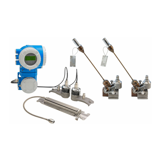
Proline Prosonic Flow P 500 HART Product description Product description The measuring system consists of a transmitter and two or one sensor sets. The transmitter and sensor sets are mounted in physically separate locations. They are interconnected by sensor cables. - Page 14 Product description Proline Prosonic Flow P 500 HART – A0043303 1 Important components of a measuring device Connection compartment cover Display module Transmitter housing with integrated ISEM electronics Electronics compartment cover Connection compartment cover: sensor cable connection Sensor for DN 15 to 65 (½ to 2½") Sensor for DN 50 to 4000 (2 to 160")
-
Page 15: Incoming Acceptance And Product
Is the envelope present with accompanying documents? • If one of the conditions is not satisfied, contact your Endress+Hauser Sales Center. • The Technical Documentation is available via the Internet or via the Endress+Hauser Operations app: Product identification→ 16. -
Page 16: Transmitter Nameplate
• The "Additional standard documentation on the device" and "Supplementary device- dependent documentation" sections • The Device Viewer: Enter the serial number from the nameplate (www.endress.com/deviceviewer) • The Endress+Hauser Operations app: Enter the serial number from the nameplate or scan the DataMatrix code on the nameplate. 4.2.1 Transmitter nameplate... -
Page 17: Sensor Nameplate
Proline Prosonic Flow P 500 HART Incoming acceptance and product identification 4.2.2 Sensor nameplate 34 5 6 Order code: Ser. no.: Date: Type.: A0043306 3 Example of sensor nameplate, "front" Name of sensor Manufacturer address/certificate holder Order code Serial number (Ser. no.) -
Page 18: Storage And Transport
Storage and transport Proline Prosonic Flow P 500 HART Storage and transport Storage conditions Observe the following notes for storage: ‣ Store in the original packaging to ensure protection from shock. ‣ Protect from direct sunlight. Avoid unacceptably high surface temperatures. -
Page 19: Mounting
Proline Prosonic Flow P 500 HART Mounting Mounting Mounting requirements 6.1.1 Mounting position Mounting location A0042039 To prevent measuring errors arising from accumulation of gas bubbles in the measuring pipe, avoid the following mounting locations in the piping: • Highest point of a pipeline. - Page 20 Mounting Proline Prosonic Flow P 500 HART Inlet and outlet runs If possible, install the sensors upstream of assemblies such as valves, T-pieces, elbows, and pumps. If this is not possible, the specified measurement accuracy of the measuring device is achieved by observing the specified minimum inlet and outlet runs with optimum sensor configuration.
- Page 21 Proline Prosonic Flow P 500 HART Mounting 3× DN 15 × DN 10 × DN 20 × DN 0…15 × DN 20 × DN 15 × DN 0…15 × DN 15 × DN A0053303 7 Inlet and outlet runs DN 50 to 4000 (2 to 160") Inlet and outlet runs DN 15 to 65 (½...
-
Page 22: Sensor Set Selection And Arrangement
Mounting Proline Prosonic Flow P 500 HART A0041975 8 Two-path measurement: examples of the horizontal arrangement of the sensor sets at a measuring point Installation of the sensor sets for measurement via 1 traverse Installation of the sensor sets for measurement via 2 traverses For horizontal orientation: non-recommended installation range (60°) - Page 23 Proline Prosonic Flow P 500 HART Mounting The sensors can be arranged in different ways: • Mounting arrangement for measurement with 1 sensor set (1 measuring path): • The sensors are located on opposite sides of the measuring pipe (offset at 180° ): measurement with 1 or 3 traverses.
- Page 24 Mounting Proline Prosonic Flow P 500 HART Two-path measurement (2 sensor sets) Vertical mounting A0042016 A0042017 13 1 traverse 14 2 traverses Horizontal mounting 120° 120° 120° 120° A0046760 A0044304 15 1 traverse 16 2 traverses Single-path measurement (1 sensor set) for order code for "Process temperature", option H, I, J...
- Page 25 Proline Prosonic Flow P 500 HART Mounting Operating frequency selection The sensors of the measuring device are available with adapted operating frequencies. For the resonance behavior of the measuring pipes, these frequencies are optimized for different properties of measuring pipes (material, pipe wall thickness) and media (kinematic viscosity).
- Page 26 Mounting Proline Prosonic Flow P 500 HART Kinematic viscosity cSt [mm 0 < v ≤ 10 10 < v ≤ 100 100 < v ≤ 1000 Nominal diameter [mm (")] Converter frequency (sensor version/number of traverses) > 300 to 1 000 (12 to 40) 1 MHz (C-100) 0.3 MHz (C-030)
-
Page 27: Environmental And Process Requirements
Proline Prosonic Flow P 500 HART Mounting Kinematic viscosity cSt [mm 0 < v ≤ 10 10 < v ≤ 100 100 < v ≤ 1000 Nominal diameter [mm (")] Converter frequency (sensor version/number of traverses) > 500 to 1 000 (20 to 40) 0.3 MHz (C-030 / 1) -
Page 28: Special Mounting Instructions
Mounting Proline Prosonic Flow P 500 HART Medium pressure range No pressure limitation For correct measurement, the static pressure of the medium must be higher than the vapor pressure. 6.1.4 Special mounting instructions Weather protection cover 280 (11.0) 255 (10.0) 146 (5.75) -
Page 29: Mounting The Measuring Device
Before commencing work: allow the system and measuring device to cool to a touch- safe temperature. High-temperature applications (> 170°C) • Order code for "Process temperature", options H, I, J • Installation for high-temperature applications may only be performed by Endress +Hauser staff or by individuals authorized and trained by Endress+Hauser. Endress+Hauser... - Page 30 Mounting Proline Prosonic Flow P 500 HART Notes on mounting Mounting the high-temperature sensors CH-050/CH-100 For detailed information on mounting the CH-050/CH-100 high-temperature sensors (order code for "Sensor version", options AG, AH), see Special Documentation on "High- temperature applications → 217".
- Page 31 Proline Prosonic Flow P 500 HART Mounting CAUTION Damage to the plastic, copper or glass pipes due to overtightening the nuts of the U- shaped screws! ‣ The use of a metal half-shell (on the opposite side of the sensor) is recommended for plastic, copper or glass pipes.
- Page 32 Mounting Proline Prosonic Flow P 500 HART 7. Push down the tensioning screw and tighten the strapping bands so they cannot slip. A0043372 24 Tighten the tensioning screws of the strapping bands. 8. If necessary, shorten the strapping bands and trim the cut edges.
- Page 33 Proline Prosonic Flow P 500 HART Mounting A0043373 25 Holder with strapping bands (medium nominal diameters), with hinged screw Mounting bolts Strapping band Tensioning screw A0044350 26 Holder with strapping bands (medium nominal diameters), without hinged screw Mounting bolts...
- Page 34 Mounting Proline Prosonic Flow P 500 HART 3. Select the mounting location of the sensors with the given sensor distance and optimum inlet run conditions,. In doing so, ensure there is nothing impeding sensor mounting over the entire circumference of the measuring pipe.
- Page 35 Proline Prosonic Flow P 500 HART Mounting A0043374 27 Holder with strapping bands (large nominal diameters) Strap bolt with guide* Strapping band* Tensioning screw *The distance between the strap bolts and strapping band lock must be at least 500 mm (20 in).
- Page 36 Mounting Proline Prosonic Flow P 500 HART 13 mm A0043375 28 Holder with welded bolts Welding seam Locking nut Hole diameter max. 8.7 mm (0.34 in) Installing sensor – small nominal diameters DN 15 to 65 (½ to 2½") Requirements •...
- Page 37 Proline Prosonic Flow P 500 HART Mounting 3. Position the sensor housing on the sensor holder. A0043377 30 Positioning the sensor housing 4. Attach the sensor housing to the sensor holder by locking the bracket into place. ...
- Page 38 Mounting Proline Prosonic Flow P 500 HART Material The following material is required for mounting: • Two strapping bands incl. mounting bolts and centering plates where necessary (already pre-assembled → 32, → 33) • Two measuring wires, each with a cable lug and a fixer to fix the strapping bands •...
- Page 39 Proline Prosonic Flow P 500 HART Mounting Procedure with a tape measure: 1. Use a tape measure to determine the pipe diameter d. 2. Mount the opposite mounting bolt at d/2 from the front mounting bolt. The distance must be d/2 = d' / 2 on both sides.
- Page 40 Mounting Proline Prosonic Flow P 500 HART 4. Fit the sensor cover on the sensor holder and turn until the sensor cover engages with a click and the arrows (▴ / ▾ "close") are pointing towards one another. 5. Insert the sensor cable into each individual sensor until the end stop.
- Page 41 Proline Prosonic Flow P 500 HART Mounting Procedure: 1. Position the strapping bands using the mounting rail [only DN50 to 600 (2 to 24"), for larger nominal diameters, measure the distance between the center of the strap bolts directly]: Fit the mounting rail with the bore identified by the letter (from the Result sensor distance / measuring aid parameter) over the mounting bolt of strapping band 1 that is fixed in place.
-
Page 42: Mounting The Transmitter Housing: Proline 500
Mounting Proline Prosonic Flow P 500 HART 8. Insert the sensor cable into each individual sensor until the end stop and tighten the locking nut. A0043386 40 Mounting the sensors and connecting the sensor cables This completes the mounting procedure. The sensors can now be connected to the transmitter via the sensor cables and the error message can be checked in the sensor check function. - Page 43 Proline Prosonic Flow P 500 HART Mounting 18 (0.71) 10 (0.39) 20 (0.79) 100 (3.94) A0029068 41 Engineering unit mm (in) 1. Drill the holes. 2. Insert wall plugs into the drilled holes. 3. Screw in the fixing screws slightly.
-
Page 44: Turning The Transmitter Housing: Proline 500
Mounting Proline Prosonic Flow P 500 HART 6.2.6 Turning the transmitter housing: Proline 500 To provide easier access to the connection compartment or display module, the transmitter housing can be turned. – – 3 mm 4 mm 7 Nm (5.2 lbf ft) A0029993 ... -
Page 45: Post-Mounting Check
Proline Prosonic Flow P 500 HART Mounting – – – 3 mm A0030035 1. Depending on the device version: Loosen the securing clamp of the connection compartment cover. 2. Unscrew the connection compartment cover. 3. Turn the display module to the desired position: max. 8 × 45° in each direction. -
Page 46: Electrical Connection
Electrical connection Proline Prosonic Flow P 500 HART Electrical connection WARNING Live parts! Incorrect work performed on the electrical connections can result in an electric shock. ‣ Set up a disconnecting device (switch or power-circuit breaker) to easily disconnect the device from the supply voltage. -
Page 47: Terminal Assignment
Proline Prosonic Flow P 500 HART Electrical connection Pulse output, phase-shifted Standard installation cable is sufficient. Relay output Standard installation cable is sufficient. Current input 0/4 to 20 mA Standard installation cable is sufficient Status input Standard installation cable is sufficient Cable diameter •... -
Page 48: Preparing The Measuring Device
Electrical connection Proline Prosonic Flow P 500 HART Terminal assignment and connection of the connecting cable: Proline 500 → 49 7.2.4 Preparing the measuring device Carry out the steps in the following order: 1. Mount the sensor and transmitter. -
Page 49: Connecting The Measuring Device: Proline 500
Proline Prosonic Flow P 500 HART Electrical connection Connecting the measuring device: Proline 500 NOTICE An incorrect connection compromises electrical safety! ‣ Have electrical connection work carried out by appropriately trained specialists only. ‣ Observe applicable federal/national installation codes and regulations. - Page 50 Electrical connection Proline Prosonic Flow P 500 HART Connecting the sensor cable to the transmitter A0044340 1. Loosen the securing clamp of the connection compartment cover. 2. Unscrew the connection compartment cover. 3. Route the two sensor cables of channel 1 through the slackened top union nut of the cable entry.
-
Page 51: Connecting The Signal Cable And The Supply Voltage Cable
Proline Prosonic Flow P 500 HART Electrical connection 7.3.2 Connecting the signal cable and the supply voltage cable A0026781 Terminal connection for supply voltage Terminal connection for signal transmission, input/output Terminal connection for signal transmission, input/output or terminal connection for network connection via service interface (CDI-RJ45;... - Page 52 Electrical connection Proline Prosonic Flow P 500 HART 10 (0.4) mm (in) – A0029815 7. Push the cable through the cable entry. To ensure tight sealing, do not remove the sealing ring from the cable entry. 8. Strip the cable and cable ends. In the case of stranded cables, also fit ferrules.
- Page 53 Proline Prosonic Flow P 500 HART Electrical connection 3 (0.12) A0029598 45 Engineering unit mm (in) 1. Use a flat-blade screwdriver to press down on the slot between the two terminal holes. 2. Remove the cable end from the terminal.
-
Page 54: Integrating The Transmitter Into A Network
Electrical connection Proline Prosonic Flow P 500 HART 7.3.3 Integrating the transmitter into a network This section only presents the basic options for integrating the device into a network. For information on the procedure to follow to connect the transmitter correctly → 49. -
Page 55: Potential Equalization
Proline Prosonic Flow P 500 HART Electrical connection Potential equalization 7.4.1 Requirements For potential equalization: • Pay attention to in-house grounding concepts • Take account of operating conditions like the pipe material and grounding • Medium, Connect the sensor and transmitter to the same electric potential •... - Page 56 Electrical connection Proline Prosonic Flow P 500 HART HART input 4...20 mA A0028763 48 Connection example for HART input with a common negative (passive) Automation system with HART output (e.g. PLC) Active barrier for power supply (e.g. RN221N) Ground cable shield at one end. The cable shield must be grounded at both ends to comply with EMC requirements;...
- Page 57 Proline Prosonic Flow P 500 HART Electrical connection Pulse/frequency output 12345 A0028761 51 Connection example for pulse/frequency output (passive) Automation system with pulse/frequency input (e.g. PLC with 10 kΩ pull-up or pull-down resistor) Power supply Transmitter: observe input values → 197...
- Page 58 Electrical connection Proline Prosonic Flow P 500 HART A0029279 54 Connection example for pulse output, phase-shifted (passive) Automation system with pulse output, phase-shifted (e.g. PLC) Power supply Transmitter: observe input values Pulse output Pulse output (slave), phase-shifted Relay output A0028760 ...
-
Page 59: Ensuring The Degree Of Protection
Proline Prosonic Flow P 500 HART Electrical connection Status input A0028764 57 Connection example for status input Automation system with status output (e.g. PLC) Power supply Transmitter Ensuring the degree of protection The measuring device fulfills all the requirements for the degree of protection IP66/67, Type 4X enclosure. - Page 60 Electrical connection Proline Prosonic Flow P 500 HART Is the terminal assignment correct ? Are dummy plugs inserted in unused cable entries and have transportation plugs been replaced with dummy plugs? Endress+Hauser...
-
Page 61: Operation Options
Proline Prosonic Flow P 500 HART Operation options Operation options Overview of operation options A0034513 Local operation via display module Computer with Web browser (e.g. Internet Explorer) or with operating tool (e.g. FieldCare, DeviceCare, AMS Device Manager, SIMATIC PDM) Field Xpert SFX350 or SFX370... -
Page 62: Structure And Function Of The Operating Menu
Operation options Proline Prosonic Flow P 500 HART Structure and function of the operating menu 8.2.1 Structure of the operating menu For an overview of the operating menu for experts: see the "Description of Device Parameters" document supplied with the device → 216... -
Page 63: Operating Philosophy
Proline Prosonic Flow P 500 HART Operation options 8.2.2 Operating philosophy The individual parts of the operating menu are assigned to certain user roles (e.g. operator, maintenance etc.). Each user role contains typical tasks within the device life cycle. Menu/parameter... -
Page 64: Access To Operating Menu Via Local Display
Operation options Proline Prosonic Flow P 500 HART Access to operating menu via local display 8.3.1 Operational display X X X X X X X 1120.50 A0029346 Operational display Device tag → 96 Status area Display range for measured values (up to 4 lines) Operating elements →... - Page 65 Proline Prosonic Flow P 500 HART Operation options Flow velocity Temperature • Density • Reference density Signal to noise ratio Acceptance rate Turbulence Signal strength °API The number and display format of the measured variables can be configured via the Format display parameter (→...
-
Page 66: Navigation View
Operation options Proline Prosonic Flow P 500 HART 8.3.2 Navigation view In the submenu In the wizard /../Operation 0091-1 /../Curr. output 1 Access stat.disp Assign curr. Operator Volume flow Locking status Display A0013993-EN A0016327-EN Navigation view Navigation path to current position... - Page 67 Proline Prosonic Flow P 500 HART Operation options Setup Is displayed: • In the menu next to the "Setup" selection • At the left in the navigation path in the Setup menu Diagnosis Is displayed: • In the menu next to the "Diagnostics" selection •...
-
Page 68: Editing View
Operation options Proline Prosonic Flow P 500 HART 8.3.3 Editing view Numeric editor +0.000 Xx – A0034250 59 For entering values in parameters (e.g. limit values) Entry display area Input screen Confirm, delete or reject entry Operating elements Text editor... - Page 69 Proline Prosonic Flow P 500 HART Operation options Operating key Meaning Enter key • Pressing the key briefly confirms your selection. • Pressing the key for 2 s confirms your entry. Escape key combination (press keys simultaneously) Close the editing view without accepting a change.
-
Page 70: Operating Elements
Operation options Proline Prosonic Flow P 500 HART 8.3.4 Operating elements Operating key Meaning Minus key In menu, submenu Moves the selection bar upwards in a picklist In wizards Goes to previous parameter In the text and numeric editor Move the entry position to the left. - Page 71 Proline Prosonic Flow P 500 HART Operation options Calling up and closing the context menu The user is in the operational display. 1. Press the and keys for longer than 3 seconds. The context menu opens. XXXXXXXXXX Setup Conf.backup...
-
Page 72: Navigating And Selecting From List
Operation options Proline Prosonic Flow P 500 HART 8.3.6 Navigating and selecting from list Different operating elements are used to navigate through the operating menu. The navigation path is displayed on the left in the header. Icons are displayed in front of the individual menus. -
Page 73: Calling Up Help Text
Proline Prosonic Flow P 500 HART Operation options The direct access code consists of a 5-digit number (at maximum) and the channel number, which identifies the channel of a process variable: e.g. 00914-2. In the navigation view, this appears on the right-hand side in the header of the selected parameter. -
Page 74: User Roles And Related Access Authorization
Operation options Proline Prosonic Flow P 500 HART Ent. access code Invalid or out of range input value Min:0 Max:9999 A0014049-EN For a description of the editing view - consisting of the text editor and numeric editor - with symbols → 68, for a description of the operating elements → 70 8.3.10... -
Page 75: Enabling And Disabling The Keypad
Proline Prosonic Flow P 500 HART Operation options 2. Enter the access code. The -symbol in front of the parameters disappears; all previously write- protected parameters are now re-enabled. 8.3.12 Enabling and disabling the keypad lock The keypad lock makes it possible to block access to the entire operating menu via local operation. -
Page 76: Requirements
Operation options Proline Prosonic Flow P 500 HART 8.4.2 Requirements Computer hardware Hardware Interface CDI-RJ45 WLAN Interface The computer must have a RJ45 The operating unit must have a WLAN interface. interface. Connection Standard Ethernet cable Connection via Wireless LAN. -
Page 77: Connecting The Device
Proline Prosonic Flow P 500 HART Operation options Measuring device: Via CDI-RJ45 service interface Device CDI-RJ45 service interface Measuring device The measuring device has an RJ45 interface. Web server Web server must be enabled; factory setting: ON For information on enabling the Web server → 81... - Page 78 Operation options Proline Prosonic Flow P 500 HART Via WLAN interface Configuring the Internet protocol of the mobile terminal NOTICE If the WLAN connection is lost during the configuration, settings made may be lost. ‣ Make sure that the WLAN connection is not disconnected while configuring the device.
-
Page 79: Logging On
Proline Prosonic Flow P 500 HART Operation options 2. Enter the IP address of the web server in the address line of the web browser: 192.168.1.212 The login page appears. 2 3 4 Device name: Device tag: Signal Status:... -
Page 80: User Interface
Operation options Proline Prosonic Flow P 500 HART 8.4.5 User interface A0029418 Function row Local display language Navigation area Header The following information appears in the header: • Device name • Device tag • Device status with status signal → 166 •... -
Page 81: Disabling The Web Server
Proline Prosonic Flow P 500 HART Operation options Working area Depending on the selected function and the related submenus, various actions can be performed in this area: • Configuring parameters • Reading measured values • Calling up help text • Starting an upload/download 8.4.6... -
Page 82: Access To The Operating Menu Via The Operating Tool
Operation options Proline Prosonic Flow P 500 HART Access to the operating menu via the operating tool The structure of the operating menu in the operating tools is the same as for operation via the local display. 8.5.1 Connecting the operating tool Via HART protocol This communication interface is available in device versions with a HART output. - Page 83 Proline Prosonic Flow P 500 HART Operation options A0028746 63 Options for remote operation via HART protocol (passive) Control system (e.g. PLC) Transmitter power supply unit, e.g. RN221N (with communication resistor) Connection for Commubox FXA195 and Field Communicator 475 Field Communicator 475 Computer with web browser (e.g.
- Page 84 Operation options Proline Prosonic Flow P 500 HART Via WLAN interface The optional WLAN interface is available on the following device version: Order code for "Display; operation", option G "4-line, illuminated; touch control + WLAN" A0041325 Transmitter with integrated WLAN antenna...
-
Page 85: Field Xpert Sfx350, Sfx370
Proline Prosonic Flow P 500 HART Operation options Configuring the Internet protocol of the mobile terminal NOTICE If the WLAN connection is lost during the configuration, settings made may be lost. ‣ Make sure that the WLAN connection is not disconnected while configuring the device. -
Page 86: Fieldcare
FieldCare Function range FDT-based (Field Device Technology) plant asset management tool from Endress+Hauser. It can configure all smart field units in a system and helps you manage them. By using the status information, it is also a simple but effective way of checking their status and condition. -
Page 87: Devicecare
DeviceCare Function range Tool for connecting and configuring Endress+Hauser field devices. The fastest way to configure Endress+Hauser field devices is with the dedicated "DeviceCare" tool. Together with the device type managers (DTMs) it presents a convenient, comprehensive solution. Innovation brochure IN01047S Source for device description files →... -
Page 88: Field Communicator 475
Operation options Proline Prosonic Flow P 500 HART 8.5.6 Field Communicator 475 Function scope Industrial handheld terminal from Emerson Process Management for remote configuration and measured value display via HART protocol. Source for device description files See information → 89 8.5.7... -
Page 89: System Integration
Proline Prosonic Flow P 500 HART System integration System integration Overview of device description files 9.1.1 Current version data for the device Firmware version 01.02.zz • On the title page of the manual • On the transmitter nameplate • Firmware version Diagnostics →... - Page 90 System integration Proline Prosonic Flow P 500 HART Dynamic variables Measured variables (HART device variables) Primary dynamic variable (PV) Volume flow Secondary dynamic variable (SV) Totalizer 1 Tertiary dynamic variable (TV) Totalizer 2 Quaternary dynamic variable (QV) Totalizer 3 The assignment of the measured variables to the dynamic variables can be modified and...
-
Page 91: Other Settings
Proline Prosonic Flow P 500 HART System integration Other settings Burst mode functionality in accordance with HART 7 Specification: Navigation "Expert" menu → Communication → HART output → Burst configuration → Burst configuration 1 to n ‣ Burst configuration 1 to n Burst mode 1 to n →... - Page 92 System integration Proline Prosonic Flow P 500 HART Parameter Description Selection / User entry Factory setting Burst variable 0 For HART command 9 and 33: select the • Not used Volume flow HART device variable or the process variable. • Volume flow •...
- Page 93 Proline Prosonic Flow P 500 HART System integration Parameter Description Selection / User entry Factory setting Min. update period Enter the minimum time span between two Positive integer 1 000 ms burst commands of burst message X. Max. update period Enter the maximum time span between two...
-
Page 94: Commissioning
Commissioning Proline Prosonic Flow P 500 HART Commissioning 10.1 Post-mounting and post-connection check Before commissioning the device: ‣ Make sure that the post-installation and post-connection checks have been performed successfully. • Checklist for "Post-mounting" check→ 45 • Checklist for "Post-connection check" → 59 10.2... - Page 95 Proline Prosonic Flow P 500 HART Commissioning X X X X X X X 20.50 Main menu Display language English Display/operat. Setup Main menu Display/operat. Setup Diagnostic / ../Setup Medium selection XXXXXXXXX XXXXXXXXX A0032222-EN 66 Navigation to "Setup" menu using the example of the local display The number of submenus and parameters can vary depending on the device version.
-
Page 96: Defining The Tag Name
Commissioning Proline Prosonic Flow P 500 HART ‣ Low flow cut off → 123 ‣ Advanced setup → 125 10.4.1 Defining the tag name To enable fast identification of the measuring point within the system, you can enter a unique designation using the Device tag parameter and thus change the factory setting. - Page 97 Proline Prosonic Flow P 500 HART Commissioning Temperature unit → 97 Density unit → 97 → 97 Reference density unit Length unit → 97 Parameter overview with brief description Parameter Description Selection Factory setting Volume flow unit Select volume flow unit.
-
Page 98: Configuring The Measuring Point
Commissioning Proline Prosonic Flow P 500 HART 10.4.3 Configuring the measuring point The "Measuring point " wizard guides you systematically through all the parameters that must be set for the configuration of the measuring point. Navigation "Setup" menu → Measuring point ‣... - Page 99 Proline Prosonic Flow P 500 HART Commissioning Liner material → 102 → 102 Liner sound velocity Liner thickness → 102 Sensor type → 102 Sensor coupling → 102 Mounting type → 102 Cable length →...
- Page 100 Commissioning Proline Prosonic Flow P 500 HART Parameter overview with brief description Parameter Prerequisite Description Selection / User Factory setting entry / User interface Measuring point configuration – Select configuration for the • 1 measuring point Depending on the measuring point. - signal path 1 sensor version •...
- Page 101 Proline Prosonic Flow P 500 HART Commissioning Parameter Prerequisite Description Selection / User Factory setting entry / User interface Pressure The Liquid hydrocarbons Enter the process pressure for 0.8 to 110 bar 1.01325 bar option is selected in the the installation. Medium parameter and the...
- Page 102 Commissioning Proline Prosonic Flow P 500 HART Parameter Prerequisite Description Selection / User Factory setting entry / User interface Pipe wall thickness – Enter the pipe wall thickness. Positive floating 3 mm point number Liner material – Select liner material. • None None • Cement •...
-
Page 103: Checking The Installation Status
Proline Prosonic Flow P 500 HART Commissioning Parameter Prerequisite Description Selection / User Factory setting entry / User interface Intermediate pipe length The 1 measuring point - 2 Enter the length of the Positive floating- 0 mm signal paths option is selected intermediate pipe between the... -
Page 104: Displaying The I/O Configuration
Commissioning Proline Prosonic Flow P 500 HART Signal to noise ratio (2917) → 104 Sound velocity (2915) → 104 → 104 Sound velocity deviation (2986) Parameter overview with brief description Parameter Description User interface Factory setting Installation status Shows the device status on installation •... -
Page 105: Configuring The Status Input
Proline Prosonic Flow P 500 HART Commissioning Navigation "Setup" menu → I/O configuration ‣ I/O configuration I/O module 1 to n terminal numbers → 105 I/O module 1 to n information → 105 → 105 I/O module 1 to n type Apply I/O configuration →... -
Page 106: Configuring The Current Input
Commissioning Proline Prosonic Flow P 500 HART Assign status input → 106 Terminal number → 106 → 106 Active level Terminal number → 106 Response time status input → 106 Terminal number → 106... -
Page 107: Configuring The Current Output
Proline Prosonic Flow P 500 HART Commissioning Failure mode → 107 Failure value → 107 Parameter overview with brief description Parameter Prerequisite Description User interface / Factory setting Selection / User entry Terminal number – Shows the terminal numbers • Not used –... - Page 108 Commissioning Proline Prosonic Flow P 500 HART Lower range value output → 109 Upper range value output → 109 → 109 Fixed current Damping current output → 109 Failure behavior current output → 109 Failure current →...
- Page 109 Proline Prosonic Flow P 500 HART Commissioning Parameter Prerequisite Description User interface / Factory setting Selection / User entry Lower range value output In Current span parameter Enter lower range value for the Signed floating-point Depends on country: (→ 108), one of the measured value range.
-
Page 110: Configuring The Pulse/Frequency
Commissioning Proline Prosonic Flow P 500 HART 10.4.9 Configuring the pulse/frequency/switch output The Pulse/frequency/switch output wizard guides you systematically through all the parameters that can be set for configuring the selected output type. Navigation "Setup" menu → Advanced setup → Pulse/frequency/switch output ‣... - Page 111 Proline Prosonic Flow P 500 HART Commissioning Parameter overview with brief description Parameter Prerequisite Description Selection / User Factory setting interface / User entry Operating mode – Define the output as a pulse, • Pulse Pulse frequency or switch output. • Frequency • Switch Terminal number –...
-
Page 112: Pulse/Frequency/Switch Output
Commissioning Proline Prosonic Flow P 500 HART Parameter Prerequisite Description Selection / User Factory setting interface / User entry Failure mode The Pulse option is selected in Select output behavior in the • Actual value No pulses the Operating mode event of a device alarm. -
Page 113: Parameter Overview With Brief Description
Proline Prosonic Flow P 500 HART Commissioning Parameter overview with brief description Parameter Prerequisite Description Selection / User Factory setting interface / User entry Operating mode – Define the output as a pulse, • Pulse Pulse frequency or switch output. • Frequency • Switch Terminal number –... - Page 114 Commissioning Proline Prosonic Flow P 500 HART Parameter Prerequisite Description Selection / User Factory setting interface / User entry Failure mode The Frequency option is Select output behavior in the • Actual value 0 Hz selected in the Operating event of a device alarm.
-
Page 115: Define The Output As A Pulse, Frequency Or
Proline Prosonic Flow P 500 HART Commissioning Configuring the switch output Navigation "Setup" menu → Pulse/frequency/switch output ‣ Pulse/frequency/switch output 1 to n Operating mode → 115 Terminal number → 115 Signal mode → 115 Switch output function →... - Page 116 Commissioning Proline Prosonic Flow P 500 HART Parameter Prerequisite Description Selection / User Factory setting interface / User entry Switch output function The Switch option is selected Select function for switch • Off in the Operating mode output. • On parameter. • Diagnostic behavior •...
-
Page 117: 10.4.10 Configuring The Relay Output
Proline Prosonic Flow P 500 HART Commissioning Parameter Prerequisite Description Selection / User Factory setting interface / User entry Switch-off value • The Switch option is Enter limit value for switch-off Signed floating-point Depends on country selected in the Operating point (process variable <... - Page 118 Commissioning Proline Prosonic Flow P 500 HART Switch-on value → 119 Switch-on delay → 119 → 119 Failure mode Switch state → 119 Powerless relay status → 119 Parameter overview with brief description Parameter Prerequisite Description User interface / ...
-
Page 119: 10.4.11 Configuring The Double Pulse Output
Proline Prosonic Flow P 500 HART Commissioning Parameter Prerequisite Description User interface / Factory setting Selection / User entry Assign status In the Relay output function Select the device function for • Off parameter, the Digital Output which to display the status. If •... -
Page 120: 10.4.12 Configuring The Local Display
Commissioning Proline Prosonic Flow P 500 HART Failure mode → 120 Invert output signal → 120 Parameter overview with brief description Parameter Description Selection / User interface / Factory setting User entry Signal mode Select the signal mode for the double pulse •... - Page 121 Proline Prosonic Flow P 500 HART Commissioning Navigation "Setup" menu → Display ‣ Display Format display → 122 Value 1 display → 122 → 122 0% bargraph value 1 100% bargraph value 1 → 122 Value 2 display →...
- Page 122 Commissioning Proline Prosonic Flow P 500 HART Parameter overview with brief description Parameter Prerequisite Description Selection / User Factory setting entry Format display A local display is provided. Select how measured values • 1 value, max. size 1 value, max. size are shown on the display.
-
Page 123: 10.4.13 Configuring The Low Flow Cut Off
Proline Prosonic Flow P 500 HART Commissioning Parameter Prerequisite Description Selection / User Factory setting entry Value 6 display A local display is provided. Select the measured value that For the picklist, see None is shown on the local display. Value 1 display parameter (→... - Page 124 Commissioning Proline Prosonic Flow P 500 HART Parameter overview with brief description Parameter Prerequisite Description Selection / User Factory setting entry Assign process variable – Select process variable for low • Off Flow velocity flow cut off. • Volume flow • Mass flow •...
-
Page 125: Advanced Settings
Proline Prosonic Flow P 500 HART Commissioning 10.5 Advanced settings The Advanced setup submenu with its submenus contains parameters for specific settings. Navigation to the "Advanced setup" submenu X X X X X X X 20.50 0104-1 Main menu Display language English Display/operat. -
Page 126: Using The Parameter To Enter The Access Code
Commissioning Proline Prosonic Flow P 500 HART ‣ WLAN settings → 133 ‣ Configuration backup → 134 ‣ → 136 Administration 10.5.1 Using the parameter to enter the access code Navigation "Setup" menu → Advanced setup Parameter overview with brief description... - Page 127 Proline Prosonic Flow P 500 HART Commissioning Totalizer 1 to n operation mode → 129 → 129 Totalizer 1 to n failure behavior Endress+Hauser...
- Page 128 Commissioning Proline Prosonic Flow P 500 HART Parameter overview with brief description Parameter Prerequisite Description Selection Factory setting Assign process variable 1 to n – Select process variable for • Off Volume flow totalizer. • Volume flow • Mass flow •...
- Page 129 Proline Prosonic Flow P 500 HART Commissioning Parameter Prerequisite Description Selection Factory setting Process variable unit 1 to n A process variable is selected Select the unit for the process • g Depends on country: in the Assign process variable variable of the totalizer.
-
Page 130: Carrying Out Additional Display Configurations
Commissioning Proline Prosonic Flow P 500 HART 10.5.4 Carrying out additional display configurations In the Display submenu you can set all the parameters associated with the configuration of the local display. Navigation "Setup" menu → Advanced setup → Display ‣... - Page 131 Proline Prosonic Flow P 500 HART Commissioning Parameter overview with brief description Parameter Prerequisite Description Selection / User Factory setting entry Format display A local display is provided. Select how measured values • 1 value, max. size 1 value, max. size are shown on the display.
- Page 132 Commissioning Proline Prosonic Flow P 500 HART Parameter Prerequisite Description Selection / User Factory setting entry 100% bargraph value 3 A selection was made in the Enter 100 % value for bar Signed floating-point Value 3 display parameter. graph display. number Decimal places 3...
-
Page 133: Wlan Configuration
Proline Prosonic Flow P 500 HART Commissioning 10.5.5 WLAN configuration The WLAN Settings submenu guides the user systematically through all the parameters that have to be set for the WLAN configuration. Navigation "Setup" menu → Advanced setup → WLAN settings ‣... -
Page 134: Configuration Management
Commissioning Proline Prosonic Flow P 500 HART Parameter Prerequisite Description Selection / User Factory setting entry / User interface Network security – Select the security type of the • Unsecured WPA2-PSK WLAN network. • WPA2-PSK • EAP-PEAP with MSCHAPv2 • EAP-PEAP MSCHAPv2 no server authentic. - Page 135 Proline Prosonic Flow P 500 HART Commissioning Navigation "Setup" menu → Advanced setup → Configuration backup ‣ Configuration backup Operating time → 135 Last backup → 135 → 135 Configuration management Backup state → 135 Comparison result →...
-
Page 136: Using Parameters For Device Administration
Commissioning Proline Prosonic Flow P 500 HART Options Description Compare The device configuration saved in the device memory is compared with the current device configuration of the HistoROM backup. Clear backup data The backup copy of the device configuration is deleted from the memory of the device. -
Page 137: Simulation
Proline Prosonic Flow P 500 HART Commissioning Using the parameter to reset the access code Navigation "Setup" menu → Advanced setup → Administration → Reset access code ‣ Reset access code → 137 Operating time Reset access code → 137... - Page 138 Commissioning Proline Prosonic Flow P 500 HART Navigation "Diagnostics" menu → Simulation ‣ Simulation Assign simulation process variable → 139 Process variable value → 139 → 140 Current input 1 to n simulation Value current input 1 to n →...
- Page 139 Proline Prosonic Flow P 500 HART Commissioning Parameter overview with brief description Parameter Prerequisite Description Selection / User Factory setting entry Assign simulation process variable – Select a process variable for • Off the simulation process that is • Volume flow activated.
-
Page 140: Protecting Settings From Unauthorized Access
Commissioning Proline Prosonic Flow P 500 HART Parameter Prerequisite Description Selection / User Factory setting entry Pulse value In the Pulse output Set and switch off the pulse 0 to 65 535 simulation parameter, the output simulation. Down-counting value option is selected. - Page 141 Proline Prosonic Flow P 500 HART Commissioning 3. Enter the access code again in the Confirm access code parameter (→ 136) to confirm. The symbol appears in front of all write-protected parameters. • Disabling parameter write protection via access code → 74.
-
Page 142: Write Protection Via Write Protection
Proline Prosonic Flow P 500 HART Via Web browser, FieldCare, DeviceCare (via CDI-RJ45 service interface), fieldbus You can only obtain a reset code from your local Endress+Hauser service organization. The code must be calculated explicitly for every device. 1. Note down the serial number of the device. - Page 143 Proline Prosonic Flow P 500 HART Commissioning 2. Setting the write protection (WP) switch on the main electronics module to the OFF position (factory setting) disables hardware write protection. No option is displayed in the Locking status parameter → 144. On the local display, the ...
-
Page 144: Operation
Operation Proline Prosonic Flow P 500 HART Operation 11.1 Reading off the device locking status Device active write protection: Locking status parameter Operation → Locking status Function scope of the "Locking status" parameter Options Description None The access authorization displayed in the Access status parameter applies →... -
Page 145: Process Variables
Proline Prosonic Flow P 500 HART Operation ‣ Input values → 150 ‣ → 151 Output values 11.4.1 Process variables The Process variables submenu contains all the parameters needed to display the current measured values for each process variable. - Page 146 Operation Proline Prosonic Flow P 500 HART Parameter overview with brief description Parameter Prerequisite Description User interface Factory setting Volume flow – Displays the volume flow that Signed floating-point – is currently measured. number Dependency The unit is taken from: Volume flow unit parameter (→...
- Page 147 Proline Prosonic Flow P 500 HART Operation Parameter Prerequisite Description User interface Factory setting For the following order code: Displays the calibration factor Positive floating- – • "Application package", option which represents the effect of point number EJ "Petroleum" pressure on the fluid. This is •...
- Page 148 Operation Proline Prosonic Flow P 500 HART Parameter Prerequisite Description User interface Factory setting NSV flow For the following order code: Displays the net volume flow Signed floating-point – • "Application package", option which is calculated from the number EJ "Petroleum"...
-
Page 149: System Values
Proline Prosonic Flow P 500 HART Operation Parameter Prerequisite Description User interface Factory setting API slope For the following order code: Shows the API slope (change –10 to 100 °API/s – • "Application package", option of API over time). Can be used EJ "Petroleum"... -
Page 150: Input Values" Submenu
Operation Proline Prosonic Flow P 500 HART Parameter overview with brief description Parameter Description User interface Signal strength Displays the current signal strength (0 to 100 dB). Signed floating-point number Assessment of the signal strength: • < 10 dB: bad •... -
Page 151: Output Values
Proline Prosonic Flow P 500 HART Operation Input values of status input The Status input 1 to n submenu contains all the parameters needed to display the current measured values for every status input. Navigation "Diagnostics" menu → Measured values → Input values → Status input 1 to n ‣... - Page 152 Operation Proline Prosonic Flow P 500 HART Parameter overview with brief description Parameter Description User interface Output current Displays the current value currently calculated for the current 3.59 to 22.5 mA output. Measured current Displays the current value currently measured for the current 0 to 30 mA output.
-
Page 153: Totalizer" Submenu
Proline Prosonic Flow P 500 HART Operation Parameter overview with brief description Parameter Description User interface Switch state Indicates the current switch state of the output. • Open • Closed Switch cycles Shows number of all performed switch cycles. Positive integer Max. -
Page 154: Adapting The Measuring Device To The Process
Operation Proline Prosonic Flow P 500 HART Parameter overview with brief description Parameter Prerequisite Description User interface Totalizer 1 to n value One of the following options is selected Displays the current totalizer counter Signed floating-point in the Assign process variable value. -
Page 155: Function Scope Of "Control Totalizer" Parameter
Proline Prosonic Flow P 500 HART Operation Parameter overview with brief description Parameter Prerequisite Description Selection / User Factory setting entry / User interface Control Totalizer 1 to n A process variable is selected Control totalizer value. • Totalize Totalize in the Assign process variable •... -
Page 156: Displaying The Measured Value History
Operation Proline Prosonic Flow P 500 HART 11.7 Displaying the measured value history The Extended HistoROM application package must be enabled in the device (order option) for the Data logging submenu to appear. This contains all the parameters for the measured value history. -
Page 157: Sound Velocity
Proline Prosonic Flow P 500 HART Operation Data logging status → 158 Entire logging duration → 158 Parameter overview with brief description Parameter Prerequisite Description Selection / User Factory setting entry / User interface Assign channel 1 The Extended HistoROM Assign process variable to •... - Page 158 Operation Proline Prosonic Flow P 500 HART Parameter Prerequisite Description Selection / User Factory setting entry / User interface Logging interval The Extended HistoROM Define the logging interval for 0.1 to 3 600.0 s 1.0 s application package is data logging. This value available.
-
Page 159: Diagnosis And Troubleshooting
Proline Prosonic Flow P 500 HART Diagnosis and troubleshooting Diagnosis and troubleshooting 12.1 General troubleshooting For local display Error Possible causes Remedial action Local display is dark, but signal output is within The cable of the display module is not plugged in... - Page 160 Diagnosis and troubleshooting Proline Prosonic Flow P 500 HART For access Fault Possible causes Remedial action Write access to parameters is not possible. Hardware write protection is enabled. Set the write protection switch on the main electronics module to the OFF position →...
- Page 161 Proline Prosonic Flow P 500 HART Diagnosis and troubleshooting Fault Possible causes Remedial action Operation with FieldCare or DeviceCare via Firewall of the PC or network is blocking Depending on the settings of the firewall used service interface CDI-RJ45 (port 8000) is not communication.
-
Page 162: Diagnostic Information Via Leds
Diagnosis and troubleshooting Proline Prosonic Flow P 500 HART 12.2 Diagnostic information via LEDs 12.2.1 Transmitter Proline 500 Different LEDs in the transmitter provide information on the device status. 1 2 3 4 5 A0029629 Supply voltage Device status Not used... -
Page 163: Diagnostic Information On Local Display
Proline Prosonic Flow P 500 HART Diagnosis and troubleshooting 12.3 Diagnostic information on local display 12.3.1 Diagnostic message Faults detected by the self-monitoring system of the measuring device are displayed as a diagnostic message in alternation with the operational display. - Page 164 Diagnosis and troubleshooting Proline Prosonic Flow P 500 HART Diagnostic behavior Symbol Meaning Alarm • Measurement is interrupted. • Signal outputs and totalizers assume the defined alarm condition. • A diagnostic message is generated. Warning • Measurement is resumed. • The signal outputs and totalizers are not affected.
-
Page 165: Calling Up Remedial Measures
Proline Prosonic Flow P 500 HART Diagnosis and troubleshooting 12.3.2 Calling up remedial measures X X X X X X X X X X X X X X 20.50 S801 Supply voltage Menu Diagnostic list Diagnostics 1 S801 Supply voltage... -
Page 166: Diagnostic Information In The Web Browser
Diagnosis and troubleshooting Proline Prosonic Flow P 500 HART 12.4 Diagnostic information in the web browser 12.4.1 Diagnostic options Any faults detected by the measuring device are displayed in the Web browser on the home page once the user has logged on. -
Page 167: Calling Up Remedy Information
Proline Prosonic Flow P 500 HART Diagnosis and troubleshooting 12.4.2 Calling up remedy information Remedy information is provided for every diagnostic event to ensure that problems can be rectified quickly. These measures are displayed in red along with the diagnostic event and the related diagnostic information. -
Page 168: Diagnostic Information In Fieldcare Or
Diagnosis and troubleshooting Proline Prosonic Flow P 500 HART 12.5 Diagnostic information in FieldCare or DeviceCare 12.5.1 Diagnostic options Any faults detected by the measuring device are displayed on the home page of the operating tool once the connection has been established. -
Page 169: Calling Up Remedy Information
Proline Prosonic Flow P 500 HART Diagnosis and troubleshooting 12.5.2 Calling up remedy information Remedy information is provided for every diagnostic event to ensure that problems can be rectified quickly: • On the home page Remedy information is displayed in a separate field below the diagnostics information. -
Page 170: Adapting The Diagnostic Information
Diagnosis and troubleshooting Proline Prosonic Flow P 500 HART 12.6 Adapting the diagnostic information 12.6.1 Adapting the diagnostic behavior Each item of diagnostic information is assigned a specific diagnostic behavior at the factory. The user can change this assignment for specific diagnostic information in the Diagnostic behavior submenu. - Page 171 Proline Prosonic Flow P 500 HART Diagnosis and troubleshooting Symbol Meaning Maintenance required Maintenance is required. The measured value remains valid. A0013957 Has no effect on the condensed status. A0023076 Endress+Hauser...
-
Page 172: Overview Of Diagnostic Information
Diagnosis and troubleshooting Proline Prosonic Flow P 500 HART 12.7 Overview of diagnostic information The amount of diagnostic information and the number of measured variables affected increase if the measuring device has one or more application packages. In the case of some items of diagnostic information, the status signal and the diagnostic behavior can be changed. - Page 173 Proline Prosonic Flow P 500 HART Diagnosis and troubleshooting Diagnostic Short text Remedy instructions Status Diagnostic number signal behavior [from the [from the factory] factory] Firmware incompatible 1. Check firmware version Alarm 2. Flash or replace electronic module Module incompatible 1.
- Page 174 Diagnosis and troubleshooting Proline Prosonic Flow P 500 HART Diagnostic Short text Remedy instructions Status Diagnostic number signal behavior [from the [from the factory] factory] I/O- 1 to n 1. Restart device Alarm communication failed 2. Check if failure recurs 3.
- Page 175 Proline Prosonic Flow P 500 HART Diagnosis and troubleshooting Diagnostic Short text Remedy instructions Status Diagnostic number signal behavior [from the [from the factory] factory] Current input 1 to n Deactivate simulation Warning simulation active Current output 1 to n...
- Page 176 Diagnosis and troubleshooting Proline Prosonic Flow P 500 HART Diagnostic Short text Remedy instructions Status Diagnostic number signal behavior [from the [from the factory] factory] Electronics temperature Increase ambient temperature Warning too low Process temperature too Reduce process temperature Warning...
-
Page 177: Pending Diagnostic Events
Proline Prosonic Flow P 500 HART Diagnosis and troubleshooting 12.8 Pending diagnostic events The Diagnostics menu allows the user to view the current diagnostic event and the previous diagnostic event separately. To call up the measures to rectify a diagnostic event: •... - Page 178 Diagnosis and troubleshooting Proline Prosonic Flow P 500 HART / ../Diagnose list Diagnostics F273 Main electronic Diagnostics 2 Diagnostics 3 A0014006-EN 71 Using the example of the local display To call up the measures to rectify a diagnostic event: •...
-
Page 179: 12.10 Event Logbook
Proline Prosonic Flow P 500 HART Diagnosis and troubleshooting 12.10 Event logbook 12.10.1 Reading out the event logbook A chronological overview of the event messages that have occurred is provided in the Events list submenu. Navigation path Diagnostics menu → Event logbook submenu → Events list / ../Eventlist... -
Page 180: 12.10.3 Overview Of Information Events
Diagnosis and troubleshooting Proline Prosonic Flow P 500 HART 12.10.3 Overview of information events Unlike a diagnostic event, an information event is displayed in the event logbook only and not in the diagnostic list. Info number Info name I1000 --------(Device ok) - Page 181 Proline Prosonic Flow P 500 HART Diagnosis and troubleshooting Info number Info name I1625 Write protection activated I1626 Write protection deactivated I1627 Web server: login successful I1628 Display: login successful I1629 CDI: login successful I1631 Web server access changed I1632...
-
Page 182: 12.11 Resetting The Measuring Device
Diagnosis and troubleshooting Proline Prosonic Flow P 500 HART 12.11 Resetting the measuring device The entire device configuration or some of the configuration can be reset to a defined state with the Device reset parameter (→ 137). 12.11.1 Function range of "Device reset" parameter... -
Page 183: 12.12 Device Information
Proline Prosonic Flow P 500 HART Diagnosis and troubleshooting 12.12 Device information The Device information submenu contains all parameters that display different information for device identification. Navigation "Diagnostics" menu → Device information ‣ Device information Device tag → 183 Serial number →... - Page 184 Diagnosis and troubleshooting Proline Prosonic Flow P 500 HART Parameter Description User interface Factory setting Device name Shows the name of the transmitter. Prosonic Flow 500 – The name can be found on the nameplate of the transmitter. Manufacturer Displays the manufacturer.
-
Page 185: 12.13 Firmware History
"Manufacturer' s information" document. The manufacturer' s information is available: • In the Download Area of the Endress+Hauser web site: www.endress.com → Downloads • Specify the following details: •... -
Page 186: Maintenance
13.2 Measuring and test equipment Endress+Hauser offers a variety of measuring and testing equipment, such as Netilion or device tests. Your Endress+Hauser Sales Center can provide detailed information on the services. -
Page 187: Repair
• The measuring devices have a modular design. • Spare parts are grouped into logical kits with the associated Installation Instructions. • Repairs are carried out by Endress+Hauser Service or by appropriately trained customers. • Certified devices can only be converted to other certified devices by Endress+Hauser Service or at the factory. -
Page 188: Disposal
Repair Proline Prosonic Flow P 500 HART 14.5 Disposal If required by the Directive 2012/19/EU on waste electrical and electronic equipment (WEEE), the product is marked with the depicted symbol in order to minimize the disposal of WEEE as unsorted municipal waste. Do not dispose of products bearing this marking as unsorted municipal waste. -
Page 189: Accessories
Various accessories, which can be ordered with the device or subsequently from Endress +Hauser, are available for the device. Detailed information on the order code in question is available from your local Endress+Hauser sales center or on the product page of the Endress+Hauser website: www.endress.com. -
Page 190: For The Sensor
Accessories Proline Prosonic Flow P 500 HART Weather protection cover Is used to protect the measuring device from the effects of the weather: e.g. rainwater, excess heating from direct sunlight. Transmitter Proline 500 Proline 500 transmitter Order number: 71343505 ... -
Page 191: Communication-Specific Accessories
Proline Prosonic Flow P 500 HART Accessories 15.2 Communication-specific accessories Accessories Description Commubox FXA195 For intrinsically safe HART communication with FieldCare via the USB port HART Technical Information TI00404F HART Loop Converter Is used to evaluate and convert dynamic HART process variables to analog current HMX50 signals or limit values. -
Page 192: Service-Specific Accessories
• As a downloadable DVD for local PC installation. Netilion lloT Ecosystem: Unlock knowledge With the Netilion lloT Ecosystem, Endress+Hauser enables you to optimize your plant performance by digitizing workflows, creating knowledge and establishing new levels of collaboration. Building decades of expertise in process automation, Endress+Hauser provides the process industry with an lloT Ecosystem that allows data-driven insights. -
Page 193: Technical Data
Proline Prosonic Flow P 500 HART Technical data Technical data 16.1 Application The measuring device is intended only for the flow measurement of liquids. To ensure that the device remains in proper operating condition for its service life, use the measuring device only for media against which the process-wetted materials are sufficiently resistant. -
Page 194: Input
(temperature, density) to the measuring device: • Analog inputs 4-20 mA • Digital inputs (via HART input or Modbus) Various temperature measuring devices can be ordered from Endress+Hauser: see "Accessories" section → 192 HART protocol The measured values are written from the automation system to the measuring device via the HART protocol. - Page 195 Proline Prosonic Flow P 500 HART Technical data Status input Maximum input values • DC –3 to 30 V • If status input is active (ON): R >3 kΩ Response time Configurable: 5 to 200 ms Input signal level • Low signal: DC –3 to +5 V •...
-
Page 196: Output
Technical data Proline Prosonic Flow P 500 HART 16.4 Output Output signal Current output 4 to 20 mA HART Order code "Output; input 1" (20): Option BA: current output 4 to 20 mA HART Signal mode Can be set to: •... - Page 197 Proline Prosonic Flow P 500 HART Technical data Pulse/frequency/switch output Function Can be configured as pulse, frequency or switch output Version Open collector Can be set to: • Active • Passive Maximum input values DC 30 V, 250 mA (passive) Open-circuit voltage DC 28.8 V (active)
- Page 198 Technical data Proline Prosonic Flow P 500 HART Number of switching Unlimited cycles Assignable functions • Disable • On • Diagnostic behavior • Limit • Volume flow • Mass flow • Flow velocity • Electronics temperature • Sound velocity • Totalizer 1-3 •...
- Page 199 Proline Prosonic Flow P 500 HART Technical data Maximum switching • DC 30 V, 0.1 A capacity (passive) • AC 30 V, 0.5 A Assignable functions • Disable • On • Diagnostic behavior • Limit • Volume flow • Mass flow •...
- Page 200 Technical data Proline Prosonic Flow P 500 HART Fault mode Choose from: • Actual value • 0 Hz • Definable value between: 2 to 12 500 Hz Switch output Fault mode Choose from: • Current status • Open • Closed...
-
Page 201: Power Supply
Proline Prosonic Flow P 500 HART Technical data Galvanic isolation The outputs are galvanically isolated: • from the power supply • from one another • from the potential equalization (PE) terminal DN 50 to 4000 (2 to 160") and non-hazardous area: The clamp-on sensors can also be mounted on cathodically protected pipes. -
Page 202: Performance Characteristics
Technical data Proline Prosonic Flow P 500 HART Overcurrent protection The device must be operated with a dedicated circuit breaker, as it does not have an element ON/OFF switch of its own. • The circuit breaker must be easy to reach and labeled accordingly. - Page 203 Proline Prosonic Flow P 500 HART Technical data The installation-specific measurement error depends on the installation conditions on site, such as the nominal diameter, wall thickness, real pipe geometry or medium. The sum of the two measurement errors is the measurement error at the measuring point.
-
Page 204: Mounting
Technical data Proline Prosonic Flow P 500 HART The measurement report shows the following maximum permissible errors: Sensor type Nominal diameter Maximum permissible errors for device C-500 (5 MHz) DN 50 (2") ±0.5% o.r. ± 5 mm/s (0.20 in/s) C-200 (2 MHz) C-100 (1 MHz) DN 100 (4") - Page 205 5 to 40%. Operating height According to EN 61010-1 • ≤ 2 000 m (6 562 ft) • > 2 000 m (6 562 ft) with additional overvoltage protection (e.g. Endress+Hauser HAW Series) Degree of protection Transmitter • IP66/67, Type 4X enclosure, suitable for pollution degree 4 •...
-
Page 206: Process
Technical data Proline Prosonic Flow P 500 HART Shock half-sine, according to IEC 60068-2-27 6 ms 50 g Rough handling shocks according to IEC 60068-2-31 Electromagnetic As per IEC/EN 61326 and NAMUR Recommendation 21 (NE 21) and 43 (NE43) compatibility (EMC) Details are provided in the Declaration of Conformity. - Page 207 Proline Prosonic Flow P 500 HART Technical data Weight Weight specifications exclusive of packaging material. Transmitter • Proline 500 aluminum: 6.5 kg (14.3 lbs) • Proline 500 cast, stainless: 15.6 kg (34.4 lbs) Sensor Including mounting material • DN 15 to 65 (½ to 2½"): 1.2 kg (2.65 lb) •...
- Page 208 Technical data Proline Prosonic Flow P 500 HART Cable entries and adapters Material • Adapter for cable entry with female thread G ½" Nickel-plated brass • Adapter for cable entry with female thread NPT ½" Only available for certain device versions: Order code for "Transmitter housing":...
-
Page 209: 16.11 Display And User Interface
Proline Prosonic Flow P 500 HART Technical data Accessories Protective cover Stainless steel, 1.4404 (316L) External WLAN antenna • Antenna: ASA plastic (acrylonitrile styrene acrylate) and nickel-plated brass • Adapter: Stainless steel and nickel-plated brass • Cable: Polyethylene • Plug: Nickel-plated brass •... - Page 210 Technical data Proline Prosonic Flow P 500 HART Operating elements • External operation via touch control (3 optical keys) without opening the housing: , , • Operating elements also accessible in the various zones of the hazardous area Remote operation →...
- Page 211 Proline Prosonic Flow P 500 HART Technical data Furthermore the device data can be managed and the network parameters can be configured. A device that has a WLAN interface (can be ordered as an option) is required for the WLAN connection: order code for "Display; operation", option G "4-line, illuminated; touch control + WLAN".
-
Page 212: 16.12 Certificates And Approvals
Technical data Proline Prosonic Flow P 500 HART Data backup Automatic • The most important device data (sensor and transmitter) are automatically saved in the DAT modules • If the transmitter or measuring device is replaced: once the T-DAT containing the... - Page 213 The device meets the legal requirements of the applicable EU Directives. These are listed in the corresponding EU Declaration of Conformity along with the standards applied. Endress+Hauser confirms successful testing of the device by affixing to it the CE mark. UKCA marking The device meets the legal requirements of the applicable UK regulations (Statutory Instruments).
-
Page 214: 16.13 Application Packages
The application packages can be ordered with the device or subsequently from Endress+Hauser. Detailed information on the order code in question is available from your local Endress+Hauser sales center or on the product page of the Endress+Hauser website: www.endress.com. - Page 215 Proline Prosonic Flow P 500 HART Technical data Data logging (line recorder): • Memory capacity for up to 1000 measured values is activated. • 250 measured values can be output via each of the 4 memory channels. The recording interval can be defined and configured by the user.
-
Page 216: 16.14 Accessories
For an overview of the scope of the associated Technical Documentation, refer to the following: • Device Viewer (www.endress.com/deviceviewer): Enter the serial number from the nameplate • Endress+Hauser Operations app: Enter serial number from nameplate or scan matrix code on nameplate. Standard documentation Brief Operating Instructions... - Page 217 Proline Prosonic Flow P 500 HART Technical data Contents Documentation code INMETRO Ex ia XA02650D INMETRO Ex ec XA02651D NEPSI Ex ia XA02652D NEPSI Ex nA XA02653D UKEX Ex ia XA02578D UKEX Ex ec XA02579D Functional Safety Manual Contents Documentation code...
-
Page 218: Index
Index Proline Prosonic Flow P 500 HART Index Connection see Electrical connection Access authorization to parameters Connection cable ......46 Read access . - Page 219 Proline Prosonic Flow P 500 HART Index Display area FieldCare ....... . . 86 For operational display .
- Page 220 Index Proline Prosonic Flow P 500 HART see Operational display Numeric editor ......68 Text editor .
- Page 221 Proline Prosonic Flow P 500 HART Index Relay output ......117 Sensor set selection and arrangement ... . 22 Relay output 1 to n (Submenu) .
- Page 222 Index Proline Prosonic Flow P 500 HART Double pulse output ..... . 153 Tools Events list ......179 For electrical connection .
- Page 224 *71633399* 71633399 www.addresses.endress.com...
Need help?
Do you have a question about the Proline Prosonic Flow P 500 and is the answer not in the manual?
Questions and answers