Sign In
Upload
Manuals
Brands
ADLINK Technology Manuals
Single board computers
cPCI-R6100
ADLINK Technology cPCI-R6100 Manuals
Manuals and User Guides for ADLINK Technology cPCI-R6100. We have
3
ADLINK Technology cPCI-R6100 manuals available for free PDF download: User Manual
ADLINK Technology
cPCI-6510 Series
User Manual
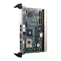
ADLINK Technology cPCI-R6100 User Manual (112 pages)
Low Power 6U CompactPCI Processor Blade with Intel Core i7 and two PMC sites
Brand:
ADLINK Technology
| Category:
Server
| Size: 2.68 MB
Table of Contents
Preface
4
Table of Contents
8
List of Tables
12
List of Figures
14
1 Overview
16
Introduction
16
Features
17
Block Diagram
18
Figure 1-1: Cpci-6510 Series Block Diagram
18
Product List
19
Package Contents
20
2 Specifications
22
Cpci-6510 Specifications
22
Table 2-1: Cpci-6510 Specifications
23
I/O Connectivity
25
Table 2-2: Cpci-6510 I/O Connectivity
25
Power Requirements
26
Table 2-3: Compactpci Input Voltage Characteristics
26
Table 2-4: Idle Mode Power Consumption
27
Table 2-5: 100% CPU Usage Power Consumption
27
Thermal Requirements
28
Figure 2-1: Core I7-610E Power Dissipation Graph (TDP 35W)
29
Figure 2-2: Core I7-620LE Power Dissipation Graph (TDP 25W)
29
Figure 2-3: Core I7-620UE Power Dissipation Graph (TDP 18W)
30
3 Functional Description
32
Processor
32
Chipset
33
Super I/O
34
Battery
34
PMC/XMC Sites
34
BIOS Recovery
35
4 Board Interfaces
36
Cpci-6510 Series Board Layout - Top Side
36
Figure 4-1: Cpci-6510 Series Board Layout - Top Side
36
Cpci-6510 Series Board Layout - Bottom Side
37
Figure 4-2: Cpci-6510 Series Board Layout - Bottom Side
37
Cpci-6510 SBC Front Panel
38
Table 4-1: Cpci-6510 Front Panel Status LED Descriptions
38
Figure 4-3: Cpci-6510 Series Front Panel Layout
38
Connector Pin Assignments
39
Table 4-2: USB Connector Pin Definition
39
Table 4-3: RJ-45 Serial Port Pin Definition
39
Table 4-4: Gbe Connector Pin Definitions
40
Table 4-5: DVI-I Connector Pin Definition
41
Table 4-6: DB-6920SAT SATA Connector Pin Definition
42
Table 4-7: PMC Connector Pin Definitions
43
Table 4-8: XMC Connector Pin Definition
45
Table 4-9: Compactflash Connector Pin Definition
46
Table 4-10: DB-6920SAT Connector Pin Definition
47
Table 4-11: Compactpci J1 Connector Pin Definition
48
Table 4-12: Compactpci J2 Connector Pin Definition
49
Table 4-13: Compactpci J3 Connector Pin Definition
50
Table 4-14: Compactpci J4 Connector Pin Definition
51
Table 4-15: Compactpci J5 Connector Pin Definition
52
Switch and Jumper Settings
53
Table 4-16: Mode Switch Settings
54
Table 4-17: PMC Bandwidth/Clock Switch Settings
54
Table 4-18: Com1/Debug Switch Settings
55
Table 4-19: Front/Rear VGA Selection Switch Settings
55
5 Getting Started
56
Hard Drive Installation
57
Compactflash Card Installation
60
PMC/XMC Module Installation
61
Installing the Cpci-6510 to the Chassis
62
Installing the RTM to the Chassis
63
6 Driver Installation
64
Driver Installation Procedure
64
7 Utilities
66
Watchdog Timer
66
Preboot Execution Environment (PXE)
71
BIOS Recovery
72
Programming NT Mode EEPROM Map
74
8 BIOS Setup Utility
76
Starting the BIOS
76
Main Setup
79
Advanced BIOS Setup
80
Chipset Configuration
90
Boot Configuration
93
Security Setup
95
Save & Exit
96
9 IPMI User Guide
98
Introduction
98
Summary of Commands Supported by BMR-AVR-Cpci
98
OEM Commands Summary Table
102
Compactpci Address Map
106
Communications with IPMC
107
IPMI Sensors List
107
Relevant Documents
107
Important Safety Instructions
108
Getting Service
110
Advertisement
ADLINK Technology cPCI-R6100 User Manual (39 pages)
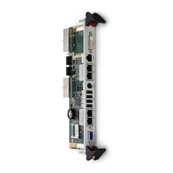
6U CompactPCI Rear Transition Module
Brand:
ADLINK Technology
| Category:
Control Unit
| Size: 1.17 MB
Table of Contents
Preface
3
Table of Contents
5
List of Figures
7
List of Tables
9
1 Introduction
11
Overview
11
Features
12
Package Contents
13
2 Specifications
15
Cpci-R6100 Series Specifications
15
Table 2-1: Cpci-R6100 Series Specifications
16
Block Diagram
17
Figure 2-1: Cpci-R6100 Functional Block Diagram
17
3 Board Interfaces
19
Cpci-R6100 Board Layout
19
Figure 3-1: Cpci-R6100 Board Layout - Component Side
19
Figure 3-2: Cpci-R6100 SW1/SW2 Locations - Solder Side
20
Cpci-R6110/6120 Board Layout
21
Figure 3-3: Cpci-R6110/6120 Board Layout
21
Connector Pin Assignments
23
Table 3-1: DVI-D Connector Pin Definition
23
Table 3-2: Front Panel COM Pin Definitions
24
Table 3-3: COM RJ-45 to DB-9 Cable Pin Definitions
24
Table 3-4: VGA Pin Definition
25
Table 3-5: DB-6920SAT/DB-6920CF Connector Pin Definition
28
Table 3-6: Compactpci Rj3 Connector Pin Definition
29
Table 3-7: Compactpci Rj5 Connector Pin Definition
30
Switch Settings
31
Table 3-8: PICMG 2.16 LAN Switch Settings
31
4 Getting Started
33
Installing a 2.5" SATA Drive
33
2Nd 2.5" SATA Drive on Cpci-R6120
35
Important Safety Instructions
37
Getting Service
39
ADLINK Technology cPCI-R6100 User Manual (40 pages)
6U Compact PCI Rear Transition Modules
Brand:
ADLINK Technology
| Category:
Single board computers
| Size: 0.39 MB
Advertisement
Advertisement
Related Products
ADLINK Technology cPCI-R6000 Series
ADLINK Technology cPCI-R6000P Series
ADLINK Technology cPCI-R6000D Series
ADLINK Technology cPCI-R6200 Series
ADLINK Technology cPCI-R6000-NF
ADLINK Technology cPCI-R6110
ADLINK Technology cPCI-R6101
ADLINK Technology cPCI-R6111
ADLINK Technology cPCI-6840 Series
ADLINK Technology cPCI-6840V
ADLINK Technology Categories
Computer Hardware
Motherboard
PCI Card
Control Unit
Controller
More ADLINK Technology Manuals
Login
Sign In
OR
Sign in with Facebook
Sign in with Google
Upload manual
Upload from disk
Upload from URL