Upright X Series Service & Parts Manual
Aerial work platform
Hide thumbs
Also See for X Series:
- Service and maintenance manual (115 pages) ,
- Operator's manual (17 pages) ,
- Service & parts manual (164 pages)
Table of Contents
Advertisement
Advertisement
Table of Contents
Troubleshooting

Related Manuals for Upright X Series


Summary of Contents for Upright X Series
- Page 1 Series Service & Parts Manual...
- Page 2 X-Series Aerial Work Platform Serial Numbers 6013 to Current When contacting UpRight for service or parts information, be sure to include the MODEL and SERIAL NUMBERS from the equipment nameplate. Should the nameplate be missing the SERIAL NUMBER is also stamped on the top right side scissor guide channel.
- Page 3 Please under- stand that these warnings cannot cover all conceivable ways in which service, whether or not recommended by UpRight, Inc., might be done, or of the possible hazard- ous consequences of each conceivable way, nor could Schematics UpRight Inc.
- Page 4 Foreword NOTES X-Series Work Platform...
-
Page 5: Table Of Contents
Contents Section Table of Contents Section Page Section Page Number Number Setting Hydraulic Pressures ......4-6 1.0 INTRODUCTION & SPECIFICATIONS Main Relief Valve ........4-6 Introduction ........... 1-1 Steering Relief Valve ........4-7 Purpose ............1-1 Counterbalance Valves ......4-7 S c o p e ............ - Page 6 Section Contents List of Illustrations Table of Contents Fig. Title P a g e (cont'd.) 1-1 X-Series Work Platform ........1-1 Section Page 2-1 Chassis Module, Right Side ......2-1 Number 6.0 SCHEMATICS 2-2 Transporting machine ........2-2 3-1 Controls and Indicators ........3-3 Introduction ...........
-
Page 7: Introduction & Specifications
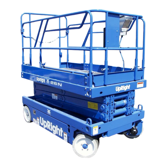
The X-Series Work Platform is a self-propelled aerial the operation and maintenance of the X-Series Work work platform designed to be used as a means of Platform manufactured by UpRight, Inc. Selma, Califor- elevating personnel and equipment and to provide a nia. (See Figure 1-1). -
Page 8: Specifications
Introduction & Specifications Section 1.2 Specifications* Table 1-1: Specifications X20N ITEM X20W X26N X31N Platform Size 28 in. x 87 in. [711 mm x 2.21 m] 44 in. x 87 in. [1.12 m x 2.21 m] 44 in. x 87 in. [1.12 m x 2.21 m] 44 in. -
Page 9: Machine Preparation
Machine Preparation Section Read, understand and follow all safety rules and 2.2 Preparation For Shipment operating instructions before attempting to operate the machine. 1. Fully lower the platform. 2. Disconnect the battery negative (-) lead from the 2.1 Preparation for Use battery terminal (Figure 2-1). -
Page 10: Transporting Work Platform
Machine Preparation Section 2.3 Transporting Work Platform 2.4 Storage No preparation is required for normal storage. Regular BY FORKLIFT maintenance per Table 4-1 should be performed. If the work platform is to be placed in long term storage (dead NOTE: Forklifting is for transporting only. storage) use the following preservation procedure. -
Page 11: Operation
NEVER use damaged equipment. (Contact UpRight for •The Tilt Alarm is activated on slopes of 2 degrees instructions. See toll free number inside front cover.) side to side and fore and aft when the machine is elevated, cutting power to Lift and Drive func- NEVER change operating or safety systems. -
Page 12: Controls And Indicators
Operation Section Table 3-1: Controls and Indicators (cont'd.) 3.2 Controls and Indicators Chassis The controls and indicators for operation of the X-Series INDEX Work Platform are shown in Figure 3-1. The name and NAME FUNCTION function of each control and indicator are listed in Emergency Stop Push red button to cut off power to all Table 3-1. -
Page 13: Battery Charger
Operation Section Pot Hole Protection Support Chassis Module, Left Side Controller X31N Model Brake Release (X31N Shown) X20N, X20W, and X26N Models Emergency Lowering Valve Handle Battery Charger Figure 3-1: Controls and Indicators X-Series Work Platform... -
Page 14: Pre-Operation Inspection
Operation Section 14. Partially lower the platform by pushing Chassis Lift 3.3 Pre-Operation Inspection Switch to DOWN and check operation of the audible lowering alarm. NOTE: Carefully read, understand and follow all safety rules, operating instructions, labels and the 15. Open the Chassis Emergency Lowering Valve (Figure Scaffold Industry Association's MANUAL OF RESPON- 3-1) to check for proper operation by pulling and SIBILITIES. -
Page 15: Travel With Platform Lowered
Operation Section 3.4 Operation ELEVATING PLATFORM Note: Before operating work platform ensure that pre-operation and safety inspection has been com- LOOK up and around for obstructions pleted, any deficiencies have been corrected and the operator has been thoroughly trained on this ma- before performing the lift function. -
Page 16: Lowering Platform
Operation Section LOWERING PLATFORM PARKING BRAKE RELEASE (Figure 3-1) 1. Position Drive/Lift Switch to LIFT. 2. Grasp the Control Lever so the Interlock Lever is Perform the following only when the machine will not depressed, pull back Control Lever to DOWN. operate under its own power and it is necessary to move the machine or when towing the machine up a grade or EMERGENCY LOWERING... -
Page 17: Maintenance
Section Maintenance 4.0 Introduction 4.1 Preventative Maintenance (Table 4-1) This section contains instructions for the maintenance of the X-Series Work Platform. Procedures for the opera- The complete inspection consists of periodic visual and tional checkout adjustment, scheduled maintenance, operational checks, together with all necessary minor and repair/removal are included. -
Page 18: Preventative Maintenance Table Key
Section Maintenance Table 4-1: Preventative Maintenance Preventative Maintenance Table Key COMPONENT INSPECTION OR SERVICES INTERVAL Y Interval Battery Check electrolyte level Daily Daily=each shift or every day System Check battery cable condition Daily 50h/30d=every 50 hours or 30 days Charge batteries Daily 250h/6m=every 250 hours or 6 months Check charger condition &... -
Page 19: Blocking Elevating Assembly
Section Maintenance 4.2 Blocking Elevating 4.2 Blocking Elevating Assembly X20N, X20W, X26N Assembly X31N (Figure 4-1) (Figure 4-2) INSTALLATION Never perform service on the work plat- 1. Park the work platform on firm level ground. form in the Elevating Assembly area while 2. -
Page 20: Battery Maintenance
Section Maintenance BATTERY CHARGING 4.3 Battery Maintenance (Figure 4-3) Electrical energy for the motor is supplied by four 6 volt Charge batteries at end of each work shift or sooner if batteries wired in series for 24 volts DC. Proper care batteries have been discharged. -
Page 21: Battery Cell Equalization
Section Maintenance 3. Charger turns on automatically after a short delay, the 4.4 Lubrication ampmeter will indicate DC charging current. 4. Charger turns off automatically when batteries are fully STEERING LINKAGE charged. Apply two to three drops of oil to each linkage bearing. BATTERY CELL EQUALIZATION Use a grease gun with multipurpose grease and apply grease to the each zerk fitting at the steering pivots. -
Page 22: Reservoir Breather/Cap
Section Maintenance 4.5 Setting Hydraulic Pressures (Figure 4-5) Check the hydraulic pressures whenever the pump, manifold or relief valves have been serviced or replaced. The hydraulic oil may be of sufficient Hydraulic Tank temperature to cause burns. Wear safety Breather/Cap/ gloves and safety glasses when handling Dipstick hot oil. -
Page 23: Steering Relief Valve
Section Maintenance STEERING RELIEF VALVE 1. Operate the work platform for 10-15 minutes to bring the hydraulic oil up to normal operating temperature. 2. Install gauge in low pressure gauge port. 3. Loosen locknut or remove cover on the Steering Relief Valve and turn adjusting screw counterclock- Right Left... -
Page 24: Pump Relief Valves
Section Maintenance 4.6 Switch Adjustments TILT SENSOR (Figure 4-7) Pump Relief Valves Introduction The Tilt Sensor has three wires; red-power (24 v in), black-ground, white-output (24 v out). To verify the sensor is working properly there are two LED's under the sensor;... -
Page 25: Down Limit Switch
Section Maintenance Elevate the platform six inches and verify DOWN LIMIT SWITCH (Figure 4-9) that the high speed circuit is inoperable. The Down Limit Switch providess power to the High If the high speed circuit is operable, the Speed Circuit when the platform is completely lowered switch is not properly aadjusted and the aand enables the Tilt Sensor/Pothole Interlock Cicuit above procedure must be repeated. -
Page 26: Hydraulic Manifold
Section Maintenance ASSEMBLY 4.7 Hydraulic Manifold (Figure 4-11) Note: Lubricate all O-rings before installation to prevent damage to O-rings. Though it is not necessary to remove the manifold to perform all maintenance procedures, a determination 1. Install fittings and plugs. should be made as to whether or not the manifold should 2. - Page 27 Section Maintenance 1. Valve Block 2. Bottom Plate 3. O-Ring 4. Plug, 9mm Expander 5. Valve, Steering 6. Valve, Lift, High Speed & Reverse 7. Valve, Drive Dump 8. Valve, Main Relief & Valve, Steering Relief 9. Valve, Counterbalance 10.Plug, Cavity 11.Fitting, 90°...
-
Page 28: Hydraulic Pump
Section Maintenance 4.8 Hydraulic Pump (Figure 4-12) 4.9 Hydraulic Drive Motors and Hubs (Figure 4-13) REMOVAL NOTE: If the hydraulic tank has not been drained, REMOVAL suitable means for plugging the hoses should be 1. Use a 1 ton (1000 Kg) capacity jack to raise the front provided to prevent excessive fluid loss. -
Page 29: Brake Cylinder
Section Maintenance 4.10 3. Remove the plugs from the hose assemblies and DISASSEMBLY connect to the drive motor. 1. Remove the set screw from the outside barrel 5. Install the wheel and secure with wheel bolts, assembly and unscrew the cylinder. torque to 80 Ft/Lbs (108 Nm). -
Page 30: Steering Cylinder
Section Maintenance 4.11 DISASSEMBLY 4.11 Steering Cylinder 1. Remove the set screw that secures the thread cap (Figure 4-15) on the cylinder barrel. REMOVAL 2. Unscrew the thread cap from the barrel. 2. Withdraw the head cap, piston and shaft assembly 1. -
Page 31: Lift Cylinder
Section Maintenance 4.12 4.12 Lift Cylinder (Figure 4-16) 1. Lift Cylinder The X20N, X20W aand X26N are all equiped 2. Pivot Pin with one Lift Cylinder. The X31N has two Lift 3. Retaining Ring Cylinders (Figure 4-17). The procedure for 4. -
Page 32: Reassembly
Section Maintenance 4.12 3. Check the bearing surfaces inside of the head cap, 2A. The shaft could be tight for a number of reasons, inside of the cylinder barrel and the rod for signs of this check is to determine if the tightness is of a scoring or excessive wear. -
Page 33: Reassembly
Section Maintenance 4.13 REASSEMBLY 1. Install new brushes and be sure they are free in the holder. Install brush with the lead wires positioned AMMETER as when received. Raise all brushes to the locked position. (See Figure 4-18B and step 3 in the Inspec- POWER SUPPLY VOLTMETER... -
Page 34: Torque Specifications
130-140 176-190 Coil nuts: 30 IN/Lbs (3 Nm) FASTENERS Use the following values to torque fasteners used on UpRight Work Platforms unless a specific torque value is called out for the part being installed. Table 4-3: Bolt Torque THREAD WIDTH... -
Page 35: Troubleshooting
Troubleshooting Section 5.0 Introduction GENERAL PROCEDURE Troubleshooting should be carried out in two steps, first Table 5-1 provides a logical sequence of tests that are thoroughly study both hydraulic and electric schematics designed to isolate problems with X-Series machines. to determine possible causes. Loose terminal connec- This table includes a list of probable causes and remedies. - Page 36 Troubleshooting Section Table 5-1: Troubleshooting TROUBLE PROBABLE CAUSE REMEDY TROUBLE PROBABLE CAUSE REMEDY All functions 1. Open control circuit Check control circuit Circuit Breaker. Work platform 1. Faulty Steering Test Steering Switch for continuity. inoperable, Circuit Breaker (CB). Reset if open (button out). will not steer Switch.
- Page 37 Troubleshooting Section Table 5-1: Troubleshooting TROUBLE PROBABLE CAUSE REMEDY Platform will 1. Emergency Down Close Emergency Down Valve, push not elevate or Valve (V7) open. in on knob. Check adjustment of Cable. elevates slowly. 2. Platform overloaded. Observe maximum load rating (See Table 1-1 ).
-
Page 38: Notes
Troubleshooting Section NOTES X-Series Work Platform... -
Page 39: Index
Section Schematics The diagrams are to be used in conjunction with Table 6.0 Introduction 5-1: Troubleshooting Guide. They allow understanding of the makeup and functions of the systems for check- This section contains electrical and hydraulic power ing, tracing, and faultfinding during troubleshooting schematics, and associated information for maintenance analysis. -
Page 40: Electrical Schematic, X31N
Section Schematics 6.1 Electrical Schematic Table 6-1: Electrical Schematic Legend, X20N, X20W, X26N REFERENCE REFERENCE DESIGNATION NAME FUNCTION LOCATION DESIGNATION NAME FUNCTION LOCATION ALM1 Alarm, Down Provides warning In front of Meter, Low Shows state of Battery Chassis Control sound (60 Hz) when electrical box Voltage/Hour charge and hours Panel. -
Page 41: Electrical Schematic, X20N, X20W, X26N
Schematics Section Table 6-1: (cont'd.) REFERENCE DESIGNATION NAME FUNCTION LOCATION Switch, Interlock Supplies power Front of joystick. to Controller. Switch, Drive/Lift Supplies power to Controller Selector High Speed circuit, bottom right. and Drive/Lift Relay and Motor Start circuit when in DRIVE Position. - Page 42 Section Schematics 6.2 Electrical Schematic Table 6-2: Electrical Schematic Legend, X31N REFERENCE REFERENCE DESIGNATION NAME FUNCTION LOCATION DESIGNATION NAME FUNCTION LOCATION ALM1 Alarm, Down Provides warning In front of Meter, Low Shows state of Battery Chassis Control sound (60 Hz) when electrical box Voltage/Hour charge and hours Panel.
-
Page 43: Electrical Schematic, X31N
Schematics Section Table 6-2: (cont'd.) REFERENCE DESIGNATION NAME FUNCTION LOCATION Switch, Interlock Supplies power Front of joystick. to Controller. Switch, Drive/Lift Supplies power to Controller Selector High Speed circuit, bottom right. and Drive/Lift Relay and Motor Start circuit when in DRIVE Position. -
Page 44: Hydraulic Schematic, X31N
Section Schematics 6.3 Hydraulic Schematic Table 6-4: Hydraulic Schematic Legend, X20N, X20W, X26N REFERENCE REFERENCE DESIGNATION NAME FUNCTION LOCATION DESIGNATION NAME FUNCTION LOCATION CYL1 Cylinder, Steering Provides force Under Chassis Valve, Reverse Prevents machine Right front of to turn front wheels. at front of machine. Counterbalance from running away Manifold Block,... -
Page 45: Hydraulic Schematic, X20N, X20W, X26N
Schematics Section Figure 6-4: Hydraulic Schematic, X20N, X20W, X26N Figure 6-5: Hydraulic Manifold, X20N, X20W, X26N X-Series Work Platform... - Page 46 Section Schematics 6.4 Hydraulic Schematic Table 6-4 : Hydraulic Schematic Legend, X31N REFERENCE REFERENCE DESIGNATION NAME FUNCTION LOCATION DESIGNATION NAME FUNCTION LOCATION CYL1 Cylinder, Steering Provides force Under Chassis Valve, Reverse Prevents machine Right front of to turn front wheels. at front of machine. Counterbalance from running away Manifold Block,...
-
Page 47: Hydraulic Schematic, X31N
Schematics Section Figure 6-6: Hydraulic Schematic, X31N Figure 6-7: Hydraulic Manifold, X31N X-Series Work Platform... - Page 48 Section Schematics NOTES 6-10 X-Series Work Platform...
-
Page 49: Index
7.0 Introduction This section lists and illustrates the replaceable assem- blies and parts of the X20N/X20W/X26N/X31N Work Platforms, as manufactured by UpRight, Inc. Each parts list contains the component parts for that assembly in- dented to show relationship where applicable. - Page 50 Section Illustrated Parts Breakdown FINAL ASSEMBLY X20N 66000-010 ITEM PART DESCRIPTION QTY. ITEM PART DESCRIPTION QTY. 66768-000 WELDMENT, TILT ALARM COVER 66001-001 BASIC ASSEMBLY 11275-003 SCREW #10-32 X 3/8 66008-010 CONTROL MODULE 11821-006 SCREW BUTTON HD 1/4-20 X 3/4 66009-010 POWER MODULE 14099-018 SCREW HHC GR5 PLTD 3/4-10 X 2 1/4...
- Page 51 Section Illustrated Parts Breakdown FINAL ASSEMBLY X20N DRAWING 1 OF 3 X20N/X20W/X26N/X31N Work Platform...
- Page 52 Section Illustrated Parts Breakdown FINAL ASSEMBLY X20N DRAWING 2 OF 3 X20N/X20W/X26N/X31N Work Platform...
- Page 53 Section Illustrated Parts Breakdown FINAL ASSEMBLY X20N DRAWING 3 OF 3 X20N/X20W/X26N/X31N Work Platform...
- Page 54 Section Illustrated Parts Breakdown FINAL ASSEMBLY X20W 66050-010 ITEM PART DESCRIPTION QTY. ITEM PART DESCRIPTION QTY. 11275-003 SCREW #10-32 X 3/8 66051-001 BASIC ASSEMBLY 11821-006 SCREW BUTTON HD 1/4-20 X 3/4 66008-010 CONTROL MODULE 14099-018 SCREW HHC GR5 PLTD 3/4-10 X 2 1/4 66009-010 POWER MODULE 11238-002...
- Page 55 Section Illustrated Parts Breakdown FINAL ASSEMBLY X20W DRAWING 1 OF 3 X20N/X20W/X26N/X31N Work Platform...
- Page 56 Section Illustrated Parts Breakdown FINAL ASSEMBLY X20W DRAWING 2 OF 3 X20N/X20W/X26N/X31N Work Platform...
- Page 57 Section Illustrated Parts Breakdown FINAL ASSEMBLY X20W DRAWING 3 OF 3 X20N/X20W/X26N/X31N Work Platform...
- Page 58 Section Illustrated Parts Breakdown FINAL ASSEMBLY X26N 66100-010 ITEM PART DESCRIPTION QTY. ITEM PART DESCRIPTION QTY. 11275-003 SCREW #10-32 X 3/8 66101-001 BASIC ASSEMBLY 11821-006 SCREW BUTTON HD 1/4-20 X 3/4 66008-010 CONTROL MODULE 14099-018 SCREW HHC GR5 PLTD 3/4-10 X 2 1/4 66009-010 POWER MODULE 11238-002...
- Page 59 Section Illustrated Parts Breakdown FINAL ASSEMBLY X26N DRAWING 1 OF 3 X20N/X20W/X26N/X31N Work Platform 7-11...
- Page 60 Section Illustrated Parts Breakdown FINAL ASSEMBLY X26N DRAWING 2 OF 3 7-12 X20N/X20W/X26N/X31N Work Platform...
- Page 61 Section Illustrated Parts Breakdown FINAL ASSEMBLY X26N DRAWING 3 OF 3 X20N/X20W/X26N/X31N Work Platform 7-13...
- Page 62 Section Illustrated Parts Breakdown FINAL ASSEMBLY X31N 66850-010 ITEM PART DESCRIPTION QTY. I T EM PART DESCRIPTION QTY. 66851-000 BASIC ASSEMBLY 66768-000 WELDMENT, TILT ALARM COVER 66008-012 CONTROL MODULE 11275-003 SCREW #10-32 X 3/8 66009-010 POWER MODULE 11821-006 SCREW BUTTON HD 1/4-20 X 3/4 66855-000 GUARDRAIL INSTALLATION 66764-000...
- Page 63 Section Illustrated Parts Breakdown FINAL ASSEMBLY X31N DRAWING 1 OF 3 X20N/X20W/X26N/X31N Work Platform 7-15...
- Page 64 Section Illustrated Parts Breakdown FINAL ASSEMBLY X31N DRAWING 2 OF 3 7-16 X20N/X20W/X26N/X31N Work Platform...
- Page 65 Section Illustrated Parts Breakdown FINAL ASSEMBLY X31N DRAWING 3 OF 3 X20N/X20W/X26N/X31N Work Platform 7-17...
- Page 66 Section Illustrated Parts Breakdown BASIC ASSEMBLY X20N 66001-001 ITEM PART DESCRIPTION QTY. 66002-010 CHASSIS ASSEMBLY 66003-000 SCISSOR ASSEMBLY 66250-010 PLATFORM WELDMENT 11248-006 NUT 3/8-16 11240-006 WASHER 3/8 FLAT 66189-000 WEAR PAD 1/4 66189-001 WEAR PAD 3/8 66189-004 WEAR PAD 1/8 66191-001 SLIDE BLOCK (BOTTOM) 61796-099...
- Page 67 Section Illustrated Parts Breakdown X20N/X20W/X26N/X31N Work Platform 7-19...
- Page 68 Section Illustrated Parts Breakdown BASIC ASSEMBLY X20W 66051-001 ITEM PART DESCRIPTION QTY. 66052-001 CHASSIS ASSEMBLY 66053-000 SCISSOR ASSEMBLY 66292-000 PLATFORM WELDMENT 11248-006 NUT 3/8-16 11240-006 WASHER 3/8 FLAT 66189-000 WEAR PAD 1/4 66189-001 WEAR PAD 3/8 66189-004 WEAR PAD 1/8 66191-001 SLIDE BLOCK (BOTTOM) 61796-099...
- Page 69 Section Illustrated Parts Breakdown X20N/X20W/X26N/X31N Work Platform 7-21...
- Page 70 Section Illustrated Parts Breakdown BASIC ASSEMBLY X26N 66101-001 ITEM PART DESCRIPTION QTY. 66052-001 CHASSIS ASSEMBLY 66103-000 SCISSOR ASSEMBLY 66292-000 PLATFORM WELDMENT 11248-006 NUT 3/8-16 11240-006 WASHER 3/8 FLAT 66189-000 WEAR PAD 1/4 66189-001 WEAR PAD 3/8 66189-004 WEAR PAD 1/8 66191-001 SLIDE BLOCK (BOTTOM) 61796-099...
- Page 71 Section Illustrated Parts Breakdown X20N/X20W/X26N/X31N Work Platform 7-23...
- Page 72 Section Illustrated Parts Breakdown BASIC ASSEMBLY X31N 66851-000 ITEM PART DESCRIPTION QTY. 66852-000 CHASSIS ASSEMBLY 66853-000 SCISSOR ASSEMBLY 66292-001 PLATFORM WELDMENT 11248-005 NUT 5/16-18 11248-006 NUT 3/8-16 66189-000 WEAR PAD 1/4 66189-001 WEAR PAD 3/8 66189-004 WEAR PAD 1/8 66191-001 SLIDE BLOCK (BOTTOM) 61796-099 GROMMET...
- Page 73 Section Illustrated Parts Breakdown X20N/X20W/X26N/X31N Work Platform 7-25...
- Page 74 Section Illustrated Parts Breakdown CHASSIS ASSEMBLY X20N 66002-010 ITEM PART DESCRIPTION QTY. ITEM PART DESCRIPTION QTY. 66717-000 WELDMENT - CHASSIS 11248-008 NUT HEX 1/2-13 UNC 11248-006 NUT HEX 3/8-16 UNC 11239-016 WASHER 1 DIA FLAT ASTM 66702-000 SLIDE PAD, STEERING LINK 11248-012 NUT HEX 3/4-10 UNC 11273-006...
- Page 75 Section Illustrated Parts Breakdown CHASSIS ASSEMBLY X20N DRAWING 1 OF 2 X20N/X20W/X26N/X31N Work Platform 7-27...
- Page 76 Section Illustrated Parts Breakdown CHASSIS ASSEMBLY X20N DRAWING 2 OF 2 7-28 X20N/X20W/X26N/X31N Work Platform...
- Page 77 Section Illustrated Parts Breakdown NOTES X20N/X20W/X26N/X31N Work Platform 7-29...
- Page 78 Section Illustrated Parts Breakdown CHASSIS ASSEMBLY X20W/X26N 66052-001 ITEM PART DESCRIPTION QTY. ITEM PART DESCRIPTION QTY. 63664-007 ORIFICE 11248-008 NUT HEX 1/2-13 UNC 11248-006 NUT HEX 3/8-16 UNC 66750-000 WELDMENT - WIDE CHASSIS 11274-016 NUT 1-14UIF SLOTTED HEX 11248-012 NUT HEX 3/4-10 UNC 11273-006 NUT JAM 3/8-16 11239-016...
- Page 79 Section Illustrated Parts Breakdown CHASSIS ASSEMBLY X20W/X26N DRAWING 1 OF 2 X20N/X20W/X26N/X31N Work Platform 7-31...
- Page 80 Section Illustrated Parts Breakdown CHASSIS ASSEMBLY X20W/X26N DRAWING 2 OF 2 7-32 X20N/X20W/X26N/X31N Work Platform...
- Page 81 Section Illustrated Parts Breakdown NOTES X20N/X20W/X26N/X31N Work Platform 7-33...
- Page 82 Section Illustrated Parts Breakdown CHASSIS ASSEMBLY X31N 66852-000 ITEM PART DESCRIPTION QTY: ITEM PART DESCRIPTION QTY: 66774-010 WELDMENT - LADDER BRACKET 11248-008 NUT HEX 1/2-13 UNC 11248-006 NUT HEX 3/8-16 UNC 66774-011 WELDMENT - LADDER BRACKET 66702-000 SLIDE PAD, STEERING LINK 11248-012 NUT HEX 3/4-10 UNC 11273-006...
- Page 83 Section Illustrated Parts Breakdown CHASSIS ASSEMBLY X31N DRAWING 1 OF 2 X20N/X20W/X26N/X31N Work Platform 7-35...
- Page 84 Section Illustrated Parts Breakdown CHASSIS ASSEMBLY X31N DRAWING 2 OF 2 7-36 X20N/X20W/X26N/X31N Work Platform...
- Page 85 Section Illustrated Parts Breakdown NOTES X20N/X20W/X26N/X31N Work Platform 7-37...
- Page 86 Section Illustrated Parts Breakdown SCISSOR ASSEMBLY X20N 66003-000 ITEM PART DESCRIPTION QTY. 66183-000 BEARING 66168-000 LIFT CYLINDER 66168-010 SEAL KIT 66201-000 WELDMENT, MID INNER TUBE 66202-000 WELDMENT, TOP & BOTTOM OUTER 66200-000 WELDMENT, BOTTOM INNER 1/4 66211-000 WELDMENT, MID OUTER 66210-000 WELDMENT, PIVOT PIN 66224-000...
- Page 87 Section Illustrated Parts Breakdown X20N/X20W/X26N/X31N Work Platform 7-39...
- Page 88 Section Illustrated Parts Breakdown SCISSOR ASSEMBLY X20W 66053-000 ITEM PART DESCRIPTION QTY. 66183-000 BEARING 66601-000 LIFT CYLINDER 66601-010 SEAL KIT 66201-000 WELDMENT, MID INNER TUBE 1/8 66240-000 WELDMENT, TOP & BOTTOM OUTER 1/8 66238-000 WELDMENT, BOTTOM INNER 3/16 66211-003 WELDMENT, MID OUTER 1/8 66210-000 WELDMENT, PIVOT PIN 66224-000...
- Page 89 Section Illustrated Parts Breakdown X20N/X20W/X26N/X31N Work Platform 7-41...
- Page 90 Section Illustrated Parts Breakdown SCISSOR ASSEMBLY X26N 66103-000 ITEM PART DESCRIPTION QTY. 66183-000 BEARING 66601-000 LIFT CYLINDER 66601-010 SEAL KIT, LIFT CYLINDER 66201-001 WELDMENT, MID INNER TUBE 1/8 66240-000 WELDMENT, TOP & BOTTOM OUTER 1/8 66238-000 WELDMENT, BOTTOM INNER 3/16 66211-002 WELDMENT, MID OUTER 1/4 66210-000...
- Page 91 Section Illustrated Parts Breakdown X20N/X20W/X26N/X31N Work Platform 7-43...
- Page 92 Section Illustrated Parts Breakdown SCISSOR ASSEMBLY X31N 66853-000 ITEM PART DESCRIPTION QTY. 66183-000 BEARING 66601-000 LIFT CYLINDER 66601-010 SEAL KIT 66201-001 WELDMENT, MID INNER TUBE 1/8 66240-000 WELDMENT, TOP & BOTTOM OUTER 1/8 66238-013 WELDMENT, BOTTOM INNER 3/16 26554-002 RIVET 1/4 POP 66210-000 WELDMENT, PIVOT PIN 66224-000...
- Page 93 Section Illustrated Parts Breakdown X20N/X20W/X26N/X31N Work Platform 7-45...
- Page 94 Section Illustrated Parts Breakdown POWER MODULE ASSEMBLY X20N/X20W/X26N/X31N 66009-010 ITEM PART DESCRIPTION QTY. 66310-010 POWER MODULE WELDMENT 27931-016 BUSHING 62791-002 LATCH COVER 11781-011 BUSHING 66735-000 WELDMENT, POT HOLE TUBE 66753-000 WELDMENT, PIVOT PIN 64350-010 SHIM 5/8ID X 1 OD X .031 STL 66803-000 POT HOLE CYLINDER 66192-000...
- Page 95 Section Illustrated Parts Breakdown X20N/X20W/X26N/X31N Work Platform 7-47...
- Page 96 Section Illustrated Parts Breakdown CONTROL MODULE ASSEMBLY X20N/X20W/X26N 66008-010 ITEM PART DESCRIPTION QTY. 66309-010 CONTROL MODULE WELDMENT 27931-016 BUSHING 11937-007 90° 12FJX-12MJ 11932-003 FITTING 45° 6FJX-6MJ 15797-000 POWER UNIT 15797-010 PUMP 15797-011 MOTOR 10145-001 BRUSHE SET (2) REQ 15797-014 SEAL KIT, PUMP 66184-004 WELD NUT 5/16-18 66780-000...
- Page 97 Section Illustrated Parts Breakdown X20N/X20W/X26N/X31N Work Platform 7-49...
- Page 98 Section Illustrated Parts Breakdown CONTROL MODULE ASSEMBLY X31N 66008-012 ITEM PART DESCRIPTION QTY. 66309-010 CONTROL MODULE WELDMENT 27931-016 BUSHING OILITE #AA-1049-14 64350-010 SHIM 5/8ID X 1 OD X .031 STL 11932-003 FITTING 45° 6FJX-6MJ 15797-000 POWER UNIT 15797-010 PUMP 15797-011 MOTOR 10145-001 BRUSH SET (2) REQ...
- Page 99 Section Illustrated Parts Breakdown X20N/X20W/X26N/X31N Work Platform 7-51...
- Page 100 Section Illustrated Parts Breakdown LOWER CONTROL BOX ASSEMBLY X20N/X20W/X26N/X31N 66014-010 ITEM PART DESCRIPTION QTY. ITEM PART DESCRIPTION QTY. 29601-013 CONN. RING 14-16 GA #10 11715-004 SCREW 6-32 UNC MACH RD HD X 1/2 11715-006 SCREW 6-32 UNC MACH RD HD X 3/4 29931-005 CONN.
- Page 101 Section Illustrated Parts Breakdown LOWER CONTROL BOX ASSEMBLY X20N/X20W/X26N/X31N DRAWING 2 OF 2 X20N/X20W/X26N/X31N Work Platform 7-53...
- Page 102 Section Illustrated Parts Breakdown CONTROLLER ASSEMBLY X20N 66013-010 ITEM PART DESCRIPTION QTY. ITEM PART DESCRIPTION QTY. 63956-003 CONN. 12 PIN 66544-012 SWITCH, INTERLOCK 63956-010 CONN. PIN MALE 66544-013 BOOT, JOYSTICK SHAFT 11252-004 SCREW 1/4-20 UNC HHC X 1/2 66805-006 PUSH BUTTON 11238-004 WASHER 1/4 LOCK 66094-010...
- Page 103 Section Illustrated Parts Breakdown CONTROLLER ASSEMBLY X20N DRAWING 2 OF 2 X20N/X20W/X26N/X31N Work Platform 7-55...
- Page 104 Section Illustrated Parts Breakdown CONTROLLER ASSEMBLY X20W/X26N/X31N 66013-012 ITEM PART DESCRIPTION QTY. ITEM PART DESCRIPTION QTY. 63956-003 CONN. 12 PIN 66544-012 SWITCH, INTERLOCK 63956-010 CONN. PIN MALE 66544-013 BOOT, JOYSTICK SHAFT 11252-004 SCREW 1/4-20 UNC HHC X 1/2 66805-006 PUSH BUTTON 11238-004 WASHER 1/4 LOCK 66094-010...
- Page 105 Section Illustrated Parts Breakdown CONTROLLER ASSEMBLY X20W/X26N/X31N DRAWING 2 OF 2 X20N/X20W/X26N/X31N Work Platform 7-57...
- Page 106 Section Illustrated Parts Breakdown VALVE MANIFOLD ASSEMBLY X20N/X20W/X26N/X31N 66017-010 ITEM PART DESCRIPTION QTY. 66099-001 VALVE BLOCK 11937-003 ADAPTER 90° 6FJX-6MJ 11941-002 ADAPTER STR 4MB-6MJ 63977-001 9MM EXPANDER PLUG 63923-007 CARTRIDGE VALVE 4 WAY 3 POS. TANDEM 63923-006 CARTRIDGE VALVE 4 WAY 2 POS REV. 63923-005 CARTRIDGE VALVE 2 WAY 12877-007...
- Page 107 Section Illustrated Parts Breakdown X20N/X20W/X26N/X31N Work Platform 7-59...
- Page 108 Section Illustrated Parts Breakdown POTHOLE VALVE ASSEMBLY X20N/X20W/X26N/X31N 66802-000 ITEM PART DESCRIPTION QTY. 66704-001 VALVE BLOCK 63973-001 VALVE, N.C. 12822-017 VALVE, CHECK 11941-001 FITTING, STR 4MB-4MJ 11941-002 FITTING, STR 4MB-6MJ 11937-001 FITTING, 90 4FJX-4MJ 11937-003 FITTING, 90 6FJX-6MJ 11934-001 FITTING, 90 4MB-4MJ 11935-001 FITTING, 45 4MB-4MJ 7-60...
- Page 109 Section Illustrated Parts Breakdown POTHOLE CYLINDER ASSEMBLY X20N/X20W/X26N/X31N 66803-000 ITEM PART DESCRIPTION QTY. 66700-001 CYLINDER 20495-012 NUT, JAM 3/4-16 66701-000 BEARING, ROD END 63973-001 VALVE N.C. 11934-001 FITTING 90° 4MB-4MJ X20N/X20W/X26N/X31N Work Platform 7-61...
- Page 110 Section Illustrated Parts Breakdown SER./ PAR. VALVE ASSEMBLY X20W/X26N/X31N 66808-000 ITEM PART DESCRIPTION QTY. 66703-001 VALVE BLOCK - SERIES PARALLEL 61797-000 VALVE, 3 WAY 2 POSITION 63924-007 VALVE, FLOW DIVIDER 11941-005 FITTING, STR 6MB-6MJ 11934-004 FITTING, 90° 6MB-6MJ 7-62 X20N/X20W/X26N/X31N Work Platform...
- Page 111 Section Illustrated Parts Breakdown NOTES X20N/X20W/X26N/X31N Work Platform 7-63...
- Page 112 Section Illustrated Parts Breakdown HYDRAULIC RESERVOIR ASSEMBLY X20N/X20W/X26N 66780-000 ITEM PART DESCRIPTION QTY. 05963-001 FILLER BREATHER 66779-000 WELDMENT RESERVOIR 11939-018 FITTING STR 12MP-6MJ 11937-003 FITTING 90° 6FJX-6MJ 66165-004 RELIEF VALVE 61818-000 FITTING SUCTION SCREEN 21305-006 FITTING PLUG MAGNETIC 11811-006 SCREW SELF TAP 10-32 X 1/2 05154-001 FILTER 11979-006...
- Page 113 Section Illustrated Parts Breakdown X20N/X20W/X26N/X31N Work Platform 7-65...
- Page 114 Section Illustrated Parts Breakdown HYDRAULIC RESERVOIR ASSEMBLY X31N 66780-010 ITEM PART DESCRIPTION QTY. 05963-001 FILLER BREATHER 66779-001 WELDMENT RESERVOIR X32N 11939-018 FITTING STR 12MP-6MJ 11937-003 FITTING 90° 6FJX-6MJ 66165-004 RELIEF VALVE 61818-000 FITTING SUCTION SCREEN 21305-006 FITTING PLUG MAGNETIC 11811-006 SCREW SELF TAP 10-32 X 1/2 05154-001 FILTER...
- Page 115 Section Illustrated Parts Breakdown X20N/X20W/X26N/X31N Work Platform 7-67...
- Page 116 Section Illustrated Parts Breakdown HOSE ASSEMBLY X20N 66011-010 ITEM PART DESCRIPTION QTY. 60861-021 HOSE ASSEMBLY X 12 60861-097 HOSE ASSEMBLY X 150 61789-011 HOSE ASSEMBLY X 11 60861-018 HOSE ASSEMBLY X 18 60861-011 HOSE ASSEMBLY X 46 60861-082 HOSE ASSEMBLY X 56 60861-047 HOSE ASSEMBLY X 54 1/2 60861-005...
- Page 117 Section Illustrated Parts Breakdown X20N/X20W/X26N/X31N Work Platform 7-69...
- Page 118 Section Illustrated Parts Breakdown HOSE ASSEMBLY X20W/X26N 66061-010 ITEM PART DESCRIPTION QTY. 60861-051 HOSE ASSEMBLY X 13 60861-097 HOSE ASSEMBLY X 150 61789-011 HOSE ASSEMBLY X 11 60861-018 HOSE ASSEMBLY X 18 60861-070 HOSE ASSEMBLY X 62 60861-076 HOSE ASSEMBLY X 80 1/2 60861-074 HOSE ASSEMBLY X 58 1/2 60861-035...
- Page 119 Section Illustrated Parts Breakdown X20N/X20W/X26N/X31N Work Platform 7-71...
- Page 120 Section Illustrated Parts Breakdown HOSE ASSEMBLY X31N 66861-000 ITEM PART DESCRIPTION QTY. 60861-051 HOSE ASSEMBLY X 13 60861-108 HOSE ASSEMBLY X 129 61789-008 HOSE ASSEMBLY X 8 3/4 60861-018 HOSE ASSEMBLY X 18 60861-070 HOSE ASSEMBLY X 62 60861-056 HOSE ASSEMBLY X 64 60861-074 HOSE ASSEMBLY X 58 1/2 60861-066...
- Page 121 Section Illustrated Parts Breakdown X20N/X20W/X26N/X31N Work Platform 7-73...
- Page 122 Section Illustrated Parts Breakdown DECK EXTENSION ASSEMBLY X20N 66006-010 ITEM PART DESCRIPTION QTY. 66251-010 WELDMENT DECK EXT. 66198-000 WEAR PAD 66193-000 STOP 66176-000 WEAR PAD 66170-000 WEAR PAD 26553-002 RIVET 3/16 DIA X .126-.250 GRIP 66195-000 PLATFORM ROLLER 66407-010 BRACKET 66256-000 WELDMENT ROLLER MOUNT 66410-000...
- Page 123 Section Illustrated Parts Breakdown X20N/X20W/X26N/X31N Work Platform 7-75...
- Page 124 Section Illustrated Parts Breakdown DECK EXTENSION ASSEMBLY X20W/X26N 66056-010 ITEM PART DESCRIPTION QTY. 66294-001 WELDMENT DECK EXT. 66198-001 WEAR PAD 66193-000 STOP 66176-001 WEAR PAD 66170-001 WEAR PAD 26553-010 RIVET 3/16 DIA X 5/8 GRIP 66195-000 PLATFORM ROLLER 66407-011 BRACKET 66256-000 WELDMENT ROLLER MOUNT 66410-000...
- Page 125 Section Illustrated Parts Breakdown X20N/X20W/X26N/X31N Work Platform 7-77...
- Page 126 Section Illustrated Parts Breakdown DECK EXTENSION ASSEMBLY X31N 66856-000 ITEM PART DESCRIPTION QTY. 66294-002 WELDMENT DECK EXT. 66198-001 WEAR PAD 66193-000 STOP 66176-001 WEAR PAD 66170-001 WEAR PAD 26553-010 RIVET 3/16 DIA X 5/8 GRIP 66195-000 PLATFORM ROLLER 66407-011 BRACKET 66256-000 WELDMENT ROLLER MOUNT 66410-000...
- Page 127 Section Illustrated Parts Breakdown X20N/X20W/X26N/X31N Work Platform 7-79...
- Page 128 Section Illustrated Parts Breakdown GUARDRAIL ASSEMBLY GUARDRAIL ASSEMBLY X20N W/O DECK EXTENSION X20N W/ DECK EXTENSION 66005-014 66005-010 ITEM PART DESCRIPTION QTY. ITEM PART DESCRIPTION QTY. 66171-003 CAP SCREW 3/8-16 X 2 1/2 (FULL THREAD) 66171-003 CAP SCREW 3/8-16 X 2 1/2 (FULL THREAD) 66518-010 KICKRAIL 66518-010...
- Page 129 Section Illustrated Parts Breakdown X20N/X20W/X26N/X31N Work Platform 7-81...
- Page 130 Section Illustrated Parts Breakdown GUARDRAIL ASSEMBLY GUARDRAIL ASSEMBLY X20W/X26N W/ DECK EXTENSION X20W/X26N W/O DECK EXTENSION 66055-010 66055-014 ITEM PART DESCRIPTION QTY. ITEM PART DESCRIPTION QTY. 11248-004 WASHER 1/4 FLAT 11248-004 WASHER 1/4 FLAT 66518-011 KICKRAIL 66518-011 KICKRAIL 66525-001 FRONT GUARDRAIL WELDMENT 66525-001 FRONT GUARDRAIL WELDMENT 03570-000...
- Page 131 Section Illustrated Parts Breakdown X20N/X20W/X26N/X31N Work Platform 7-83...
- Page 132 Section Illustrated Parts Breakdown GUARDRAIL ASSEMBLY X31N 66855-000 ITEM PART DESCRIPTION QTY. 65814-003 WELDMENT, LOWER GUARDRAIL R.H. 65814-002 WELDMENT, LOWER GUARDRAIL L.H. 65815-002 WELDMENT, UPPER GUARDRAIL R.H. 65816-002 WELDMENT, UPPER GUARDRAIL L.H. 65805-003 WELDMENT, TOP SWING ARM 66516-001 PLUG 1 3/16 DIA 11248-006 NUT HEX ESNA 3/8-16UNC 66171-003...
- Page 133 Section Illustrated Parts Breakdown X20N/X20W/X26N/X31N Work Platform 7-85...
- Page 134 Section Illustrated Parts Breakdown LABEL ASSEMBLY X20N 66010-010 ITEM PART DESCRIPTION QTY. 61683-006 LABEL UPRIGHT 61683-004 LABEL UPRIGHT 05221-000 LABEL MAINTAIN BATTERY 66552-000 LABEL HYDR GAS 66551-000 LABEL MAX LOAD 250 LBS 66557-000 LABEL MAX LOAD 750 LBS 14222-003-99 LABEL FORK LIFT HERE...
- Page 135 Section Illustrated Parts Breakdown X20N/X20W/X26N/X31N Work Platform 7-87...
- Page 136 Section Illustrated Parts Breakdown LABEL ASSEMBLY X20W 66060-010 ITEM PART DESCRIPTION QTY. 61683-006 LABEL UPRIGHT 61683-004 LABEL UPRIGHT 05221-000 LABEL MAINTAIN BATTERY 66552-000 LABEL HYDR GAS 66551-000 LABEL MAX LOAD 250 LBS 66566-000 LABEL MAX LOAD 1000 LBS 14222-003-99 LABEL FORK LIFT HERE...
- Page 137 Section Illustrated Parts Breakdown X20N/X20W/X26N/X31N Work Platform 7-89...
- Page 138 Section Illustrated Parts Breakdown LABEL ASSEMBLY X26N 66110-010 ITEM PART DESCRIPTION QTY. 61683-006 LABEL UPRIGHT 61683-004 LABEL UPRIGHT 05221-000 LABEL MAINTAIN BATTERY 66552-000 LABEL EXPLOSIVE GAS WARNING 66551-000 LABEL MAX LOAD 250 LBS 66566-000 LABEL MAX LOAD 1000 LBS 14222-003-99 LABEL FORK LIFT HERE...
- Page 139 Section Illustrated Parts Breakdown X20N/X20W/X26N/X31N Work Platform 7-91...
- Page 140 Section Illustrated Parts Breakdown LABEL ASSEMBLY X31N 66860-000 ITEM PART DESCRIPTION QTY. 61683-006 LABEL UPRIGHT 61683-004 LABEL UPRIGHT 05221-000 LABEL MAINTAIN BATTERY 66552-000 LABEL EXPLOSIVE GAS WARNING 66551-000 LABEL MAX LOAD 250 LBS 66557-001 LABEL MAX LOAD 700 LBS 14222-003-99...
- Page 141 Section Illustrated Parts Breakdown X20N/X20W/X26N/X31N Work Platform 7-93...
- Page 142 Section Illustrated Parts Breakdown POWER TO PLATFORM,OPTION X20/X26 66610-010 ITEM PART DESCRIPTION QTY. 11715-004 SCREW, RD. HD 6-32 X 1/2 11248-047 NUT, ESNA #6-32 08942-001 OUTLET, HUBBELL #61CM65 66505-000 BRACKET 29495-099 WIRE, 14GA 3 COND. 50FT 11715-006 SCREW TR HD 6-32 X 3/4 129961-000 INLET PLUG, HUBBELL #5278C 29961-001 SEAL, INLET PLUG...
- Page 143 Section Illustrated Parts Breakdown FLASHING AMBER LIGHT, OPTION X20/X26 66611-010 ITEM PART DESCRIPTION QTY. 29825-002 DOIODE 11826-004 SCREW, MACH RD HD 10-32 UNF X 1/2 12848-004 LIGHT - FLASHING 13283-002 CABLE TIE 29496-099 WIRE, 16 GA. 2 COND CABLE 9 FT 29620-003 CONN BUTT 12 - 10 66506-000 BRACKET - LIGHT MOUNT...
- Page 144 Section Illustrated Parts Breakdown HORN, OPTION X20N/X20W/X26N/X31N 66614-010 ITEM PART DESCRIPTION QTY. 29496-099 WIRE, 2 COND CABLE 5 FT 29615-002 CONNECTOR PUSH 66807-002 HORN 63917-000 SWITCH PUSHBUTTON 7-96 X20N/X20W/X26N/X31N Work Platform...
- Page 145 Section Illustrated Parts Breakdown X20N/X20W/X26N/X31N Work Platform 7-97...
- Page 146 Section Illustrated Parts Breakdown PROPORTIONAL CONTROL, OPTION PROPORTIONAL CONTROL, OPTION X20W,X26N,X32 X20N 66628-012 66628-010 ITEM PART DESCRIPTION QTY. ITEM PART DESCRIPTION QTY. 65374-000 PROPORTIONAL VALVE BLOCK 65374-000 PROPORTIONAL VALVE BLOCK 63986-002 PROPORTIONAL VALVE 63986-002 PROPORTIONAL VALVE 11979-008 O-RING 11979-008 O-RING 14412-016 SCREW #10-24 X 2 SOC HD 14412-016...
- Page 147 Section Illustrated Parts Breakdown PROPORTIONAL CONTROL, OPTION X20/X20W/X26N DRAWING 1 OF 3 X20N/X20W/X26N/X31N Work Platform 7-99...
- Page 148 Section Illustrated Parts Breakdown PROPORTIONAL CONTROL, OPTION X20W/X26N\X31N DRAWING 2 OF 3 7-100 X20N/X20W/X26N/X31N Work Platform...
- Page 149 Section Illustrated Parts Breakdown PROPORTIONAL CONTROL, OPTION X20N DRAWING 3 OF 3 X20N/X20W/X26N/X31N Work Platform 7-101...
- Page 150 Section Illustrated Parts Breakdown PROPORTIONAL CONTROLLER, OPTION X20N 66020-010 ITEM PART DESCRIPTION QTY. ITEM PART DESCRIPTION QTY. 66544-013 BOOT, JOYSTICK SHAFT 63956-003 CONN. 12 PIN 63956-010 CONN. PIN MALE 66805-006 PUSH BUTTON 66094-010 PANEL, CONTROLLER L.H. 11252-004 SCREW 1/4-20 UNC HHC X 1/2 11238-004 WASHER 1/4 LOCK 66095-010...
- Page 151 Section Illustrated Parts Breakdown PROPORTIONAL CONTROLLER,OPTION X20N DRAWING 2 OF 2 X20N/X20W/X26N/X31N Work Platform 7-103...
- Page 152 Section Illustrated Parts Breakdown PROPORTIONAL CONTROLLER, OPTION X20W\X26N 66020-012 ITEM PART DESCRIPTION QTY. ITEM PART DESCRIPTION QTY. 63956-003 CONN. 12 PIN 66544-012 SWITCH, INTERLOCK 63956-010 CONN. PIN MALE 66544-013 BOOT, JOYSTICK SHAFT 11252-004 SCREW 1/4-20 UNC HHC X 1/2 66805-006 PUSH BUTTON 11238-004 WASHER 1/4 LOCK...
- Page 153 Section Illustrated Parts Breakdown PROPORTIONAL CONTROLLER,OPTION X20W\X26N DRAWING 2 OF 2 X20N/X20W/X26N/X31N Work Platform 7-105...
- Page 154 Section Illustrated Parts Breakdown ALL MOTION ALARM, OPTION X20N/X20W/X26N/X31N 66616-010 ITEM PART DESCRIPTION QTY. 29825-002 DIODE 29620-003 CONN. BUTT 12-10 29610-018 CONN. FORK 12-10 7-106 X20N/X20W/X26N/X31N Work Platform...
- Page 155 Section Illustrated Parts Breakdown AIR TO PLATFORM, OPTION X20N/X20W/X26N/X31N 66629-001 ITEM PART DESCRIPTION QTY. ITEM PART DESCRIPTION QTY. 11249-003 LOCK NUT ESNA HEX #10-32 63594-001 BRACKET 11826-008 SCREW RD. HD. MACH #10-32 15770-099 HOSE 3/8 SYNFLEX 3600-06 50 FT 12728-000 COUPLING M AIR 64274-002 FITTING HOSE...
- Page 156 Section Illustrated Parts Breakdown 5 FT. PLATFORM EXTENSION, OPTION X20N 66041-000 ITEM PART DESCRIPTION QTY. 66040-000 WELDMENT PLATFORM 5 FT. EXT. 66198-000 WEAR PAD 66193-000 STOP 66176-000 WEAR PAD 66170-000 WEAR PAD 26553-012 RIVET 3/16 DIA X 3/4 GRIP 66195-000 PLATFORM ROLLER 66407-000 BRACKET...
- Page 157 Section Illustrated Parts Breakdown 5 FT PLATFORM EXTENSION, OPTION X20N DRAWING 1 OF 2 X20N/X20W/X26N/X31N Work Platform 7-109...
- Page 158 Section Illustrated Parts Breakdown 5 FT PLATFORM EXTENSION, OPTION X20N DRAWING 2 OF 2 7-110 X20N/X20W/X26N/X31N Work Platform...
- Page 159 Section Illustrated Parts Breakdown HOUR/LOW VOLTAGE INDICATOR, OPTION X20N/X20W/X26N/X31N 66613-000 ITEM PART DESCRIPTION QTY. 29959-000 HR/LOW VOLTAGE IND. 29931-003 CONN. PUSH TERM 29456-099 WIRE 16 GA. YEL X 15" 1.33FT 29454-099 WIRE 16 GA. RED X 12" 1 FT 29601-013 CONN.
- Page 160 Section Illustrated Parts Breakdown GENERATOR, OPTION X20N/X26N 66615-000 ITEM PART DESCRIPTION QTY. 11715-006 SCREW RD. HD. 6-32 X 3/4 LG. 11248-047 NUT ESNA 6-32 08942-001 OUTLET 66505-000 BRACKET 29495-099 WIRE 14 GA. 3 COND 50 FT 29961-001 SEAL, INLET PLUG 29938-000 THREE PRONG PLUG - 90 11248-004...
- Page 161 Section Illustrated Parts Breakdown X20N/X20W/X26N/X31N Work Platform 7-113...
- Page 162 Section Illustrated Parts Breakdown REMOVABLE CONTROLLER OPTION X20N/X20W/X26N/X31N 61898-001 ITEM PART DESCRIPTION QTY. 28800-003 PLUG CONNECTOR (FEMALE) 28800-004 PIN CONTACT (MALE) 28800-015 PLUG SEALING 28800-016 RECEPTACLE CONNECTOR W/CLMP (MALE) 28800-005 SOCKET CONTACT (FEMALE) 11248-006 NUT HEX ESNA 3/8-16 11240-006 WASHER 3/8 STD FLAT 30719-001 110 VAC BRACKET 30719-002...
- Page 163 Section Illustrated Parts Breakdown REMOVABLE CONTROLLER OPTION X20N/X20W/X26N/X31N DRAWING 2 OF 2 X20N/X20W/X26N/X31N Work Platform 7-115...
- Page 164 Section Illustrated Parts Breakdown 7-116 X20N/X20W/X26N/X31N Work Platform...
- Page 165 Call Toll Free in U.S.A. 1-800-926-LIFT For Parts: 1-888-UR-PARTS UpRight, Inc. 1775 Park Street Selma, California 93662 TEL: 209/891-5200 FAX: 209/896-9012 PARTSFAX: 209/896-9244 P/N 60571-002 060571-002-9708-5-D...
- Page 166 Call Toll Free in U.S.A. 1-800-926-LIFT For Parts: 1-888-UR-PARTS UpRight, Inc. 1775 Park Street Selma, California 93662 TEL: 209/891-5200 FAX: 209/896-9012 PARTSFAX: 209/896-9244 P/N 60571-002 060571-002-9708-5-D...
Need help?
Do you have a question about the X Series and is the answer not in the manual?
Questions and answers
Upright Inc 3400 Repair Manual. Model # 068002-01 SN21158
@Larry Halse Looking for instructions to replace o-rings on lift cylinder.
The repair manual for the UpRight X Series can be found in the X Series Service & Parts Manual. If you need service or parts information, include the model and serial numbers from the equipment nameplate. If the nameplate is missing, the serial number is stamped on the top right side scissor guide channel.
For further assistance, you can contact UpRight at:
- Toll-Free in the U.S.: 1-800-926-LIFT
- For Parts: 1-888-UR-PARTS
- Address: 1775 Park Street, Selma, California 93662
- Phone: (559) 891-5200
- Fax: (559) 891-9012
- Parts Fax: (559) 896-9244
This answer is automatically generated
I HAVE A UPLIFT X20 IM LOOKING IM TRYING TO FIND PAGE 4/2 PINTURE OF ELECTRIMOTOR
The picture of the electric motor for the UpRight X Series is on page 3-23. Page 4-2 contains a figure of the hydraulic test port.
This answer is automatically generated