Upright X Series Service & Parts Manual
Work platforms
Hide thumbs
Also See for X Series:
- Service and maintenance manual (115 pages) ,
- Operator's manual (17 pages) ,
- Service & parts manual (166 pages)
Table of Contents
Advertisement
Advertisement
Table of Contents
Troubleshooting

Related Manuals for Upright X Series


Summary of Contents for Upright X Series
- Page 1 060571-005...
- Page 2 MANUAL X Series Serial Numbers 15020 to current When contacting UpRight for service or parts information, be sure to include the MODEL and SERIAL NUMBERS from the equipment nameplate. Should the nameplate be missing, the SERIAL NUMBER is also stamped on top of the top right side scissor guide channel towards the front of the machine.
- Page 3 Indicates a potentially hazardous situation which, if not avoided, could result in death or serious injury. C A U T I O N Indicates a potentially hazardous situation which, if not avoided, may result in minor or moderate injury. NOTE: Gives helpful information. 060571-005 X Series Work Platform Page I...
- Page 4 Please understand that these warnings cannot cover all conceivable ways in which service, whether or not recommended by UpRight, Inc., might be done, or of the possible hazardous consequences of each conceivable way, nor could UpRight, Inc., investigate all such ways.
-
Page 5: Table Of Contents
2.8 Specifications ..........2-16 060571-005 X Series Page i... - Page 6 3.4 UpRight Connectors ........
- Page 7 Checking Pump Pressures ........... . .4-2 4.3 Upright Motor Controller Diagnostics ....... . 4-3 4.4 Measured Voltage at I/O Board .
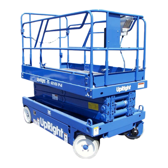
- Page 8 Introduction Figure 1-1: X Series Work Platform .......1-1 Section 2 Operation and Specifications Figure 2-1: Chassis Controls .
- Page 9 Figure 4-2: Motor Controller ........4-3 060571-005 X Series Page v...
- Page 10 Table 4-3: Electrical Troubleshooting Table ..........4-6 060571-005 Page vi X Series...
-
Page 11: Introduction
NTRODUCTION URPOSE The purpose of this service and parts manual is to provide instructions and illustrations for the operation and maintenance of this work platform manufactured by UpRight, Inc., of Selma, Cali- fornia. COPE The manual includes procedures for proper operation, maintenance, adjustment, and repair of this product as well as recommended maintenance schedules and troubleshooting. -
Page 12: Chassis
Introduction 1.2 - General Description HASSIS The chassis is a structural frame that supports all the components of the X Series work platform. URPOSE OF QUIPMENT The objective of the work platform is to provide a quickly deployable, self propelled, variable height work platform to elevate personnel and materials to overhead work areas. - Page 13 AFTER USE secure the work platform against unauthorized use by turning the key switch off and removing the key. NEVER replace any component or part with anything other than original UpRight replacement parts without the manufacturer’s consent. 060571-005...
-
Page 14: Operation And Specifications
Operation and Specifications 2.1 - Introduction 2.1 I NTRODUCTION This manual covers operation of the X Series Self-Propelled Work Platform. This manual must be stored on the machine at all times. 2.2 P PERATION AND AFETY NSPECTION Carefully read, understand and follow all safety rules, operating instructions, labels, and the Scaf- fold Industry Association’s MANUAL OF RESPONSIBILITIES. -
Page 15: Operation And Specifications
30. Lower the platform completely. 31. Push the Platform Emergency Stop Switch to check for proper operation. All the machine functions should be disabled. Pull out the Platform Emergency Stop Switch to resume. 060571-005 X Series Work Platform Page 2-3... -
Page 16: Operation
8. Engage the Interlock Switch and move the Control Handle to FORWARD or REVERSE to travel in the desired direction. The speed of the machine will vary depending on how far from center the Control Handle is moved. 060571-005 Page 2-4 X Series Work Platform... -
Page 17: Steering
OWERING THE LATFORM 1. Turn the Lift/Drive Switch to LIFT. 2. Engage the Interlock Switch and pull back on the Control Handle to lower the platform. 060571-005 X Series Work Platform Page 2-5... -
Page 18: Emergency Lowering
1. Open the Emergency Lowering Valve by pulling and holding the knob. 2. To close, release the knob. The platform will not elevate if the Emergency Lowering Valve is open. Emergency Lowering Knob 060571-005 Page 2-6 X Series Work Platform... -
Page 19: Lower The Guardrails, X26N
2. Rotate the front and rear upper guardrails outward and secure them to the opposite side guardrails using the retaining pins. 3. Hang the controller on the side guardrail. W A R N I N G Before operating machine, guardrails must be securely fastened in their proper position. 060571-005 X Series Work Platform Page 2-7... -
Page 20: After Use Each Day
REAR 22% grade. W A R N I N G Never tow faster than 1 ft./sec. (0,3m/sec.) Never operate the work platform with the parking brakes released. Serious injury or damage could result. 060571-005 Page 2-8 X Series Work Platform... -
Page 21: 2.4 - Transporting The Work Platform
C A U T I O N Front tie down lugs are not to be used to lift the work platform. Overtightening of chains or straps attached to tie down lugs may result in damage to the work platform. 060571-005 X Series Work Platform Page 2-9... -
Page 22: Maintenance
3. X31N - Rotate the Scissor Brace clockwise until the POSITION locking pin engages. 4. Lower the platform by pushing the Chassis Lift/ Lower Switch to LOWER to completely lower the platform. BRACE RESTS ON PIN WHEN IN BLOCKING POSITION X31N 060571-005 Page 2-10 X Series Work Platform... -
Page 23: Battery Maintenance
Wash hands after handling. Battery fluid is highly corrosive. Thoroughly rinse away any spilled fluid with clean water. Always replace batteries with UpRight batteries or manufacturer approved replacements weighing 62 lbs. (28 kg.) each. Figure 2-10: Power Module •... -
Page 24: Battery Charging
3. The battery charger turns on automatically after a short delay. NOTE: The battery charger circuit must be used with a GFI (Ground Fault Circuit Interrupt) outlet. DO NOT operate the machine while the charger is plugged in. 060571-005 Page 2-12 X Series Work Platform... - Page 25 Proper label installation is required. All of these labels shall be present and in good condition before operating the work platform. Be sure to read, under- stand, and follow these labels BEFORE operating the work platform. 060571-005 X Series Work Platform Page 2-13...
-
Page 26: Preventative Maintenance
The preventative maintenance table has been designed for machine service and maintenance repair. Please photocopy the following page and use the table as a checklist when inspecting the machine for service. 060571-005 Page 2-14 X Series Work Platform... -
Page 27: 2.7 - Preventative Maintenance Checklist Maintenance Checklist
Wipe clean Check for peeling, missing, or unreadable Labels Daily labels & replace Check for leaks at mating surfaces Hydraulic Pump Check for hose fitting leaks Daily Check mounting bolts for proper torque 060571-005 X Series Work Platform Page 2-15... -
Page 28: Specifications
40 in. [1,02 m] High Toeboard 6 in. [152 mm] High Specifications are subject to change without notice. Hot weather or heavy use may reduce performance. Meets or exceeds all applicable requirements of OSHA and ANSI A92.6-1999 060571-005 Page 2-16 X Series Work Platform... -
Page 29: Maintenance
Plant, Year, Month, Day. ARKER i.e.: XXXX 6 11 29 - means Plant XXXX, 1996, month 11 (November), day 29. stamps month, day and year on each hose. AYCO 060571-005 X Series Work Platform Page 3-1... -
Page 30: Special Tools
(UpRight P/N 030898-000) • Inclinometer 3.4 U IGHT ONNECTORS UpRight connectors are designed so that connector parts, contacts, or electrical cables may be replaced without replacing the entire connector. Figure 3-1: UpRight Connector Kit Small Kit Large Kit Figure 3-2: Plugs and Receptacles, UpRight Connectors... -
Page 31: Female Connector (Receptacle)
4. Replace or recrimp the wires and contacts. Refer to “Crimping” procedure. ELEASING OCKING INGERS Figure 3-3: Locking Finger, UpRight Connector 1. The Locking Fingers can be released following the removal of the Locking Wedge of either the male or female connector. -
Page 32: Supporting Elevating Assembly
2. Rotate the Scissor Brace up and over towards the rear so that it rests on the cylinder mount, stowed position. 3. Push the Chassis Lift Switch to the DOWN position, and completely lower the platform. 4. Turn the Chassis Key Switch to DECK. 060571-005 Page 3-4 X Series Work Platform... -
Page 33: X31N
Scissor Brace will clear the pivot pins. 2. Rotate the Scissor Brace counterclockwise until it locks into position parallel with the scissor arm. 3. Push the Chassis Lift Switch to the DOWN position, and completely lower the platform. 060571-005 X Series Work Platform Page 3-5... -
Page 34: Battery Maintenance
Under such conditions, a 4 hour equalize charge once a week in the early afternoon will improve the state of charge and battery life. 060571-005 Page 3-6 X Series Work Platform... -
Page 35: Battery Cell Equalization
Do not check the specific gravity in a cell to which water has just been added. If there is not enough electrolyte in a fully charged cell to obtain a sample for the hydrometer, add water and continue charging for one to two hours to adequately mix the water and electrolyte. 060571-005 X Series Work Platform Page 3-7... -
Page 36: Switch Adjustments
5. Elevate the platform six inches and verify that the high speed circuit is inoperable. If the high speed circuit is operable, the switch is not properly adjusted and the above procedure must be repeated. 060571-005 Page 3-8 X Series Work Platform... -
Page 37: Control Handle
2. Remove and replace defec- tive parts. Refer to Section 6 Rocker Pin for repair part numbers. Rocker, Steering Right Handle Half Steering Switch (2) Switch, Interlock Left Handle Half Boot, Handle Lever, Interlock Hall Effect Device 060571-005 X Series Work Platform Page 3-9... -
Page 38: 3.8 - Motor Controller And I/O Board Dip Switch Settings
Result Two Speed Mode (not used) Proportional Control Not used Depression Mechanism extends Part when platform is raised Serial Down alarm only Down and Reverse alarm Drive and Down alarm All Motion alarm 060571-005 Page 3-10 X Series Work Platform... -
Page 39: 3.9 - Hydraulic Oil Tank And Filter
9. Fill the hydraulic reservoir with ISO #46 hydraulic oil until the oil is up to the full mark on the dipstick. ESERVOIR REATHER Clean the breather/cap at the same time that the oil filter is replaced. Use cleaning solvent and blow dry with clean, dry compressed air. Figure 3-15: Hydraulic Tank 060571-005 X Series Work Platform Page 3-11... -
Page 40: 3.10 - Setting Hydraulic Pressures
7. Tighten locknut or replace Main Relief Valve cover and torque to 6 Ft/Lbs (8 Nm.). Figure 3-16: Hydraulic Manifold Steering Relief Valve Counterbalance Valves Test Port Lift Relief Valve Main Relief Valve 060571-005 Page 3-12 X Series Work Platform... -
Page 41: Steering Relief Valve
9. Check the settings by slowly moving the Control Lever FORWARD, then REVERSE, check- ing the gauge to ensure pressures are properly set. Readjust as needed. 10. Tighten locknuts on valves to 6 Ft/Lbs (8 Nm). Remove blocks and lower the work platform to the ground. 060571-005 X Series Work Platform Page 3-13... -
Page 42: Hydraulic Manifold
4. Operate each hydraulic function, and check for proper function and leaks. 5. Check the level in the hydraulic fluid tank. 6. Adjust all relief valves mounted on the Hydraulic Manifold according to instructions in “3.10 Setting Hydraulic Pressures” on Page 3-12. 060571-005 Page 3-14 X Series Work Platform... -
Page 43: Figure 3-17: Hydraulic Manifold
23. 3 POS - 4 WAY SOLENOID W/ COILS 10. MAIN RELIEF VALVE (2800 PSI (193 BAR) (DRIVE) 11. 2 POS - 4 WAY SOLENOID W/ COIL (LIFT) 12. COIL 13. 3 POS - 4 WAY SOLENOID W/ COILS (STEER) 060571-005 X Series Work Platform Page 3-15... -
Page 44: Hydraulic Pump
4. Install the wheel and secure with wheel bolts. Torque to 80 Ft/Lbs (108 Nm). 5. Remove the jackstands, lower the jack, and remove. Operate the drive system and check for leaks. 060571-005 Page 3-16 X Series Work Platform... -
Page 45: Brake Cylinder
3.14 B RAKE YLINDER The brake cylinder is located between the rear wheels at the rear of the chassis. NOTE: The X31N has two brake cylinders. All other X Series machines have only one. Figure 3-20: Brake Cylinder 1.Brake Cylinder EMOVAL 2.Shoulder Bolt... -
Page 46: Cleaning And Inspection
3. Check the inside surface of the cylinder barrel for scoring or excessive wear. 4. Check the piston and headcap for scoring or excessive wear. 5. Inspect the surface of the shaft for scoring or excessive wear. 060571-005 Page 3-18 X Series Work Platform... -
Page 47: Assembly
1. Place cylinder, piston end down, onto pivot pins. Install locknut and pin clip. 2. Connect the hoses to the fittings. 3. Lift the platform, then lower it and move the machine. Repeat this several times to check for proper operation. 060571-005 X Series Work Platform Page 3-19... -
Page 48: Removal
3. Check the bearing surfaces inside of the head cap, inside of the cylinder barrel and the rod for signs of scoring or excessive wear. 4. Replace all seals and O-rings. 060571-005 Page 3-20 X Series Work Platform... -
Page 49: Reassembly
5. Lubricate the piston and install the piston and rod assembly in the barrel tube. 6. Thread the head cap into the barrel tube and hand tighten, then turn ¼ turn further with a wrench. 7. Install the Down Valve and fittings. 060571-005 X Series Work Platform Page 3-21... -
Page 50: Installation
6. Unplug hydraulic hoses and attach to the cylinder. Replace hydraulic fluid removed from the Lift Cylinder. 7. Test with weight at rated platform load to check system operation. Check for leaks and level of fluid. 060571-005 Page 3-22 X Series Work Platform... -
Page 51: Electric Motor
3. Armature should be checked for grounds and clear of this shorted turns. Refinish commutator surface if space. pitted or excessively worn. 4. Brushes should be checked for wear and to ensure that they are free in the brush holders. 060571-005 X Series Work Platform Page 3-23... -
Page 52: 3.19 - Torque Specifications
PECIFICATIONS YDRAULIC OMPONENTS NOTE: Always lubricate threads with clean hydraulic oil prior to installation Use the following values to torque hydraulic components used on UpRight Work Platforms. Table 3-1: Torque Specifications for Hydraulic Components Type: SAE Part Series Cartridge Poppet... -
Page 53: Table 3-3: Torque Specifications For Metric Fasteners, U.s. Customary Units
285,728 1157 1543 333,923 1352 1803 252,450 1136 1515 349,223 1572 2095 408,128 1837 2450 312,300 1546 2061 432,015 2138 2851 504,885 2500 3332 367,650 1985 2647 508,582 2746 3662 594,368 3210 4279 060571-005 X Series Work Platform Page 3-25... - Page 54 Maintenance 3.19 - Torque Specifications OTES 060571-005 Page 3-26 X Series Work Platform...
-
Page 55: Introduction
3-4. Unplug the machine or disconnect the battery when replacing or testing the continuity of any electrical component. Tel: 1-559-891-5200 IGHT FAX: 1-559-891-8931 Tel: +353-1-202-4100 IGHT RELAND FAX: +353-1-202-4105 060571-005 X Series Work Platform Page 4-1... -
Page 56: Troubleshooting
• Flow Meter with Pressure Gauge (UpRight P/N 067040-000) • 0-69 bar (0-1000 psi (0-69 bar) Hydraulic Pressure Gauge with Adapter Fittings (UpRight P/ N 014124-010) • 0-207 bar (0-3000 psi (0-207 bar) Hydraulic Pressure Gauge with Adapter Fittings (UpRight P/N 014124-030) •... -
Page 57: 4.3 - Upright Motor Controller Diagnostics
Troubleshooting 4.3 - Upright Motor Controller Diagnostics 4.3 U PRIGHT OTOR ONTROLLER IAGNOSTICS Batteries must be fully charged before troubleshooting. Check/Repair all connections before replacing any components Table 4-1: LED Fault Codes LASH EANING TATUS ORRECTIVE CTION Power to the controller and the... -
Page 58: Measured Voltage At I/O Board
24 Volts = Line Contactor OFF / 0 Volts = Line Contactor ON 24 Volts = No Direction Solenoid Allowed / 0 Volts = Direction Solenoid Allowed to Activate Accelerator 3.5 Volts to 0 Volts / Minimum to Maximum Speed 060571-005 Page 4-4 X Series Work Platform... -
Page 59: Hydraulic
X X X X Steering Relief Tank Steering Right/Left Valve Lift Valve Down/Emergency Lowering Valve Depression Mechanism Retract Valve Depression Mechanism Extend Valve Forward/Reverse Valve X X X X X X Series/Parallel Valve (2) Counterbalance Valve 060571-005 X Series Work Platform Page 4-5... -
Page 60: Electric
Platform Steering Switch (2) X X X X X X X X X X X X X X Tilt Sensor Steering Solenoid (right) Steering Solenoid (left) Platform Lift Solenoid Reverse Solenoid Forward Solenoid 060571-005 Page 4-6 X Series Work Platform... - Page 61 Troubleshooting 4.6 - Electric OMPONENT Series/Parallel Solenoid(2) Depression Mechanism Extension Solenoid Down Solenoid Depression Mechanism Retraction Solenoid 060571-005 X Series Work Platform Page 4-7...
- Page 62 Troubleshooting 4.6 - Electric OTES 060571-005 Page 4-8 X Series Work Platform...
-
Page 63: Introduction
Legend: Hydraulic Schematic, X20W, X26N--066781-020..5-8 Legend: Hydraulic Schematic, X31N--066781-021 ....5-10 060571-005 X Series Work Platform Page 5-1... -
Page 64: Electrical
Solenoid Depression Mechanism Retracts depression Depression SOL3B Retraction mechanism bars Mechanism Cylinder Solenoid Shifts forward/reverse valve SOL4A Reverse Solenoid Hydraulic Manifold to reverse Shifts forward/reverse valve SOL4B Forward Solenoid Hyraulic Manifold to forward 060571-005 Page 5-2 X Series Work Platform... - Page 65 Schematics - 5.2 - Electrical SOL1A SOL1B SOL2A SOL4A SOL4B SOL3A SOL2B SNSR SOL3B SOL3B Control Handle 060571-005 X Series Work Platform Page 5-3...
-
Page 66: Legend: Electrical Schematic, X20W, X26N, X31N--066769-020
Shift between high and low speed drive SOL5 Control Module Solenoids (2) speed drive Stops lift assembly at lower limit, cuts out high speed Limit Switch Platform Controls drive when platform is elevated 060571-005 Page 5-4 X Series Work Platform... - Page 67 Schematics - 5.2 - Electrical SOL1A SOL1B SOL2A SOL4A SOL4B SOL5 SOL5 SOL3A Control Handle SNSR SOL2B SOL3B SOL3B 060571-005 X Series Work Platform Page 5-5...
-
Page 68: Legend: Hydraulic Schematic, X20N--065615-023
Provides oil control for DM Depression nism Retract Valve Mechanism Cylinder Forward/Reverse Provides oil control for drive Hydraulic Manifold or lift functions Valve Prevents machine from Counterbalance running away on slopes; Hydraulic Manifold Valve (2) cushions stops 060571-005 Page 5-6 X Series Work Platform... - Page 69 Schematics - 5.3 - Hydraulics 060571-005 X Series Work Platform Page 5-7...
-
Page 70: Legend: Hydraulic Schematic, X20W, X26N--066781-020
Provides oil control for drive Hydraulic Manifold or lift functions Valve Series/Parallel Controls drive speed Series/Parallel Block Valve (2) Prevents machine from Counterbalance running away on slopes; Hydraulic Manifold Valve (2) cushions stops 060571-005 Page 5-8 X Series Work Platform... - Page 71 Schematics - 5.3 - Hydraulics 060571-005 X Series Work Platform Page 5-9...
-
Page 72: Legend: Hydraulic Schematic, X31N--066781-021
Hydraulic Manifold Valve (2) cushions stops Lowers Platform manually Emergency Down when machine doesn’t Chassis Valve function Velocity Fuse (2) Prevents free fall of platform Lift Cylinder in the event of a pressure loss 060571-005 Page 5-10 X Series Work Platform... - Page 73 Schematics - 5.3 - Hydraulics 060571-005 X Series Work Platform Page 5-11...
- Page 74 Schematics - 5.3 - Hydraulics 060571-005 Page 5-12 X Series Work Platform...
- Page 75 Schematics - 5.3 - Hydraulics #2 Plug #2 #4 Plug #4 #6 Plug #6 #8 Plug #8 060571-005 X Series Work Platform Page 5-13...
- Page 76 Schematics - 5.3 - Hydraulics Depression Mechanism Cylinder Series/Parallel Drive Block 060571-005 Page 5-14 X Series Work Platform...
- Page 77 066611-010 ........6-79 060571-005 X Series Work Platform Page 6-1...
- Page 78 066611-020 ........6-86 060571-005 Page 6-2 X Series Work Platform...
- Page 79 Illustrated Parts Breakdown - 6.1 - Introduction OTES 060571-005 X Series Work Platform Page 6-3...
-
Page 80: Hydraulics
CABLE ASSY X 40 066713-001 WELDMENT, DOOR HINGE 062125-011 CABLE ASSY X 9 013283-002 CABLE MOUNT 064195-005 CABLE ASSY X 5 010154-001 COVER BATTERY TERMINAL 029601-039 CONN RING 5/16 10-12 Drawing # 1 of 4 060571-005 Page 6-4 X Series Work Platform... - Page 81 Illustrated Parts Breakdown - 6.1 - Final Assembly-X20N Drawing # 2 of 4 060571-005 X Series Work Platform Page 6-5...
- Page 82 Illustrated Parts Breakdown - 6.1 - Final Assembly-X20N Drawing # 3 of 4 060571-005 Page 6-6 X Series Work Platform...
- Page 83 Illustrated Parts Breakdown - 6.1 - Final Assembly-X20N Drawing # 4 of 4 060571-005 X Series Work Platform Page 6-7...
-
Page 84: Figure 3-8: Power Module
WASHER 3/4 FLAT 062125-011 CABLE ASSY X 9 066713-001 WELDMENT, DOOR HINGE 064195-005 CABLE ASSY X 5 013283-002 CABLE MOUNT 010154-001 COVER BATTERY TERMINAL 029601-039 CONN RING 5/16 10-12 Drawing # 1 of 4 060571-005 Page 6-8 X Series Work Platform... - Page 85 Illustrated Parts Breakdown - 6.1 - Final Assembly-X20W Drawing # 2 of 4 060571-005 X Series Work Platform Page 6-9...
- Page 86 Illustrated Parts Breakdown - 6.1 - Final Assembly-X20W Drawing # 3 of 4 060571-005 Page 6-10 X Series Work Platform...
- Page 87 Illustrated Parts Breakdown - 6.1 - Final Assembly-X20W Drawing # 4 of 4 060571-005 X Series Work Platform Page 6-11...
- Page 88 CABLE ASSY X 40 066713-001 WELDMENT, DOOR HINGE 062125-011 CABLE ASSY X 9 013283-002 CABLE MOUNT 064195-005 CABLE ASSY X 5 010154-001 COVER BATTERY TERMINAL 029601-039 CONN RING 5/16 10-12 Drawing # 1 of 4 060571-005 Page 6-12 X Series Work Platform...
- Page 89 Illustrated Parts Breakdown - 6.1 - Final Assembly-X26N Drawing # 2 of 4 060571-005 X Series Work Platform Page 6-13...
- Page 90 Illustrated Parts Breakdown - 6.1 - Final Assembly-X26N Drawing # 3 of 4 060571-005 Page 6-14 X Series Work Platform...
- Page 91 Illustrated Parts Breakdown - 6.1 - Final Assembly-X26N Drawing # 4 of 4 060571-005 X Series Work Platform Page 6-15...
- Page 92 WASHER 3/4 FLAT 029601-039 CONN RING 5/16 10-12 066713-001 WELDMENT, DOOR HINGE 014252-004 NUTSERT 1/4-20 013283-002 CABLE MOUNT 063497-020 PLUG MERCURY WIRE ASSY 011252-010 SCREW HHC 1/4-20 X 1 1/4 Drawing # 1 of 4 060571-005 Page 6-16 X Series Work Platform...
- Page 93 Illustrated Parts Breakdown - 6.1 - Final Assembly-X31N Drawing # 2 of 4 060571-005 X Series Work Platform Page 6-17...
- Page 94 Illustrated Parts Breakdown - 6.1 - Final Assembly-X31N Drawing # 3 of 4 060571-005 Page 6-18 X Series Work Platform...
- Page 95 Illustrated Parts Breakdown - 6.1 - Final Assembly-X31N Drawing # 4 of 4 060571-005 X Series Work Platform Page 6-19...
- Page 96 SCREW HHC 3/8-16 X 3 LG 066189-001 WEAR PAD 3/8 011240-006 WASHER 3/8 FLAT 066189-004 WEAR PAD 1/8 011248-006 NUT 3/8-16 066191-001 SLIDE BLOCK (BOTTOM) 011248-005 NUT 5/16-18 061796-099 GROMMET FT .63 066183-001 BEARING EAGLE PICHER #323632 060571-005 Page 6-20 X Series Work Platform...
- Page 97 SCREW HHC 3/8-16 X 4 LG 066189-001 WEAR PAD 3/8 011240-006 WASHER 3/8 FLAT 066189-004 WEAR PAD 1/8 011248-006 NUT 3/8-16 066191-001 SLIDE BLOCK (BOTTOM) 011248-005 NUT 5/16-18 061796-099 GROMMET FT .63 066183-001 BEARING EAGLE PICHER #323632 060571-005 X Series Work Platform Page 6-21...
- Page 98 SCREW HHC 3/8-16 X 4 LG 066189-001 WEAR PAD 3/8 011240-006 WASHER 3/8 FLAT 066189-004 WEAR PAD 1/8 011248-006 NUT 3/8-16 066191-001 SLIDE BLOCK (BOTTOM) 011248-005 NUT 5/16-18 061796-099 GROMMET FT .63 066183-001 BEARING EAGLE PICHER #323632 060571-005 Page 6-22 X Series Work Platform...
- Page 99 WEAR PAD 3/8 065369-099 HOSE GUARD, NYLON 066189-004 WEAR PAD 1/8 011248-006 NUT 3/8-16 066191-001 SLIDE BLOCK (BOTTOM) 011248-005 NUT 5/16-18 061796-099 GROMMET FT .63 066183-001 BEARING EAGLE PICHER #323632 066222-001 MOUNTING PIN 060571-005 X Series Work Platform Page 6-23...
-
Page 100: Figure 3-20: Brake Cylinder
WELDMENT - LADDER BRACKET L.H. 05104-000 SEAL GREASE 066731-025 LADDER BRACKET STANDOFF 011775-011 CONE BEARING 066325-000 HUB - FRONT 066773-000 HUB ASSY 063559-006 BOLT SHOULDER 3/8 X 2 011848-009 CLEVIS PIN 5/8 X 2 060571-005 Page 6-24 X Series Work Platform... - Page 101 Illustrated Parts Breakdown - 6.1 - Chassis Assembly-X20N Drawing # 1 of 2 060571-005 X Series Work Platform Page 6-25...
- Page 102 Illustrated Parts Breakdown - 6.1 - Chassis Assembly-X20N Drawing # 2 of 2 060571-005 Page 6-26 X Series Work Platform...
- Page 103 Illustrated Parts Breakdown - 6.1 - Chassis Assembly-X20N OTES 060571-005 X Series Work Platform Page 6-27...
- Page 104 SEAL GREASE 066731-025 LADDER BRACKET STANDOFF 011775-011 CONE BEARING 066325-000 HUB - FRONT 066773-000 HUB ASSY 063559-006 BOLT SHOULDER 3/8 X 2 011848-009 CLEVIS PIN 5/8 X 2 066152-001 STEERING LINK WELDMENT L.H. 060571-005 Page 6-28 X Series Work Platform...
- Page 105 Illustrated Parts Breakdown - 6.1 - Chassis Assembly-X20W,X26N Drawing # 1 of 2 060571-005 X Series Work Platform Page 6-29...
- Page 106 Illustrated Parts Breakdown - 6.1 - Chassis Assembly-X20W,X26N Drawing # 2 of 2 060571-005 Page 6-30 X Series Work Platform...
- Page 107 Illustrated Parts Breakdown - 6.1 - Chassis Assembly-X20W,X26N OTES 060571-005 X Series Work Platform Page 6-31...
- Page 108 CLEVIS PIN 5/8 X 2 011775-011 CONE BEARING 066152-001 STEERING LINK WELDMENT L.H. 066773-000 HUB ASSY 066190-011 BEARING - STRIP 26553-012 RIVET 3/16 DIA X 1 1/8 GRIP 066311-001 WELDMENT - STEERING ANGLE LH 060571-005 Page 6-32 X Series Work Platform...
- Page 109 Illustrated Parts Breakdown - 6.1 - Chassis Assembly-X31N Drawing # 1 of 2 060571-005 X Series Work Platform Page 6-33...
- Page 110 Illustrated Parts Breakdown - 6.1 - Chassis Assembly-X31N Drawing # 2 of 2 060571-005 Page 6-34 X Series Work Platform...
- Page 111 Illustrated Parts Breakdown - 6.1 - Chassis Assembly-X31N OTES 060571-005 X Series Work Platform Page 6-35...
-
Page 112: Lift Cylinder
WELDMENT, PIVOT PIN 011252-006 SCREW HHC GR5 1/4-20 X 3/4 066224-000 PIN, LIFT CYLINDER 064462-035 PLUG, 3/4” DIA CAP PLUG 066225-000 PIN, SHAFT LOCKING 011764-032 RET RING TRUARC #5100-200 066214-000 WELDMENT, SAFETY STAND 060571-005 Page 6-36 X Series Work Platform... - Page 113 WELDMENT, PIVOT PIN 011252-006 SCREW HHC GR5 1/4-20 X 3/4 066224-000 PIN, LIFT CYLINDER 064462-035 PLUG, 3/4” DIA. CAP PLUG 066225-000 PIN, SHAFT LOCKING 011764-032 RET RING TRUARC #5100-200 066214-000 WELDMENT, SAFETY STAND 060571-005 X Series Work Platform Page 6-37...
- Page 114 SCREW HHC 5/8-11 X 3 1/2 011246-010 NUT 5/8-11 THIN HEX 066224-001 PIN, LIFT CYLINDER 066226-001 CHANNEL, CABLE 066210-002 WELDMENT, PIVOT PIN 066574-002 WELDMENT, TORSION ARM R.H. 011239-010 WASHER, FLAT 5/8 ASTM 064462-035 PLUG, 3/4” DIA. CAP PLUG 060571-005 Page 6-38 X Series Work Platform...
- Page 115 Illustrated Parts Breakdown - 6.1 - Scissor Assembly-X26N 060571-005 X Series Work Platform Page 6-39...
- Page 116 FITTING STR 6MB-6MJ 066814-000 WELDMENT, SCISSOR BRACE 03570-001 RETAINING RING 026554-002 RIVET 1/4 POP 011937-003 FITTING 6FJX-6MJ 90 066210-012 WELDMENT, PIVOT PIN 066226-002 HOSE CHANNEL 064462-035 PLUG, 3/4” DIA. CAP PLUG 066638-000 TEE, BULKHEAD, 6MJ-6MJ-6MJ 060571-005 Page 6-40 X Series Work Platform...
- Page 117 Illustrated Parts Breakdown - 6.1 - Scissor Assembly-X31N 060571-005 X Series Work Platform Page 6-41...
- Page 118 RIVET 3/16 DIA X .126-.250 GRIP 066171-003 SCREW HHC 3/8-16 X 2 1/2 066195-000 PLATFORM ROLLER 011240-004 WASHER 1/4 FLAT 066407-010 BRACKET 011238-006 WASHER 3/8 LOCK 066256-000 WELDMENT ROLLER MOUNT 067185-000 DECKLOCK ASSY-SLIDEOUT 060571-005 Page 6-42 X Series Work Platform...
- Page 119 026553-010 RIVET 3/16 DIA X 5/8 GRIP 011252-006 SCREW HHC 1/4-20 X 3/4 066195-000 PLATFORM ROLLER 011240-004 WASHER 1/4 FLAT 066407-011 BRACKET 011238-006 WASHER 3/8 LOCK 066127-000 WELDMENT ROLLER MOUNT 067185-000 DECKLOCK ASSY-SLIDEOUT 060571-005 X Series Work Platform Page 6-43...
- Page 120 WELDMENT, SIDE EXT R.H. 027966-005 SAFTY WALK 6 X 24 065804-002 WELDMENT, SIDE EXT L.H. 026553-004 RIVET 3/16 DIA X 3/8 GRIP 026553-008 RIVET 3/16 DIA X 1/2 GRIP 03570-000 RETAINING PIN ASSY 060571-005 Page 6-44 X Series Work Platform...
- Page 121 011254-020 SCREW 3/8-16 HHC X 2 1/2 066498-000 WELDMENT, GATE LATCH 011240-006 WASHER 3/8 FLAT 066257-000 WELDMENT SIDE RAIL 011248-006 NUT 3/8-16 HEX 066261-005 WELDMENT, END RAIL 063133-000 CHAIN ASS’Y 015748-002 REPAIR LAPLINK 060571-005 X Series Work Platform Page 6-45...
- Page 122 WELDMENT, GATE LATCH 011254-008 SCREW 3/8-16 HHC X 1 066126-000 WELDMENT SIDE RAIL 011240-006 WASHER 3/8 FLAT 066125-003 WELDMENT, END RAIL 011248-006 NUT 3/8-16 HEX 063133-000 CHAIN ASS’Y 015748-002 REPAIR LAPLINK 011248-005 NUT 5/16-18 060571-005 Page 6-46 X Series Work Platform...
- Page 123 ASSEMBLY CHAIN GATE 065805-003 WELDMENT, TOP SWING ARM 03570-000 RETAINING PIN ASSEMBLY 011248-006 NUT HEX ESNA 3/8-16UNC 066516-001 PLUG 1 3/16 DIA 011254-018 SCREW HHC 3/8-16UNC X 2 1/4 011248-005 NUT HEX ESNA 5/16-18UNC 060571-005 X Series Work Platform Page 6-47...
- Page 124 WELDMENT, POT HOLE TUBE 064350-010 SHIM 5/8ID X 1 OD X .031 STL 066753-000 WELDMENT, PIVOT PIN 011240-006 WASHER 3/8 STD FLAT 011252-008 SCREW HHC 1/4-20 X 1 066803-000 CYLINDER ASSEMBLY 066700-010 SEAL KIT, CYLINDER 060571-005 Page 6-48 X Series Work Platform...
- Page 125 Illustrated Parts Breakdown - 6.1 - Power Module 060571-005 X Series Work Platform Page 6-49...
- Page 126 HORN DUAL TONE 011253-006 SCREW HHC GR5 5/16-18 X 3/4 011252-006 SCREW RD HD 6-32 X 3/4 011252-008 SCREW HHC GR5 1/4-20 X 1 011248-004 NUT, 1/4-20 ESNA 011248-005 NUT HEX ESNA 5/16-18 060571-005 Page 6-50 X Series Work Platform...
- Page 127 Illustrated Parts Breakdown - 6.1 - Control Module 060571-005 X Series Work Platform Page 6-51...
-
Page 128: Figure 3-16: Hydraulic Manifold
064843-000 FLOW DIVIDER VALVE (1.0 GPM) 063973-001 2 POS POPPET VALVE W/ COIL (DEPRESSION MECHANISM) 101120-033 COIL 063965-001 FITTING GAUGE 064841-000 CHECK VALVE 063923-021 3 POS - 4 WAY SOLENOID W/ COILS (DRIVE) 060571-005 Page 6-52 X Series Work Platform... - Page 129 Illustrated Parts Breakdown - 6.1 - Hydraulic Manifold 060571-005 X Series Work Platform Page 6-53...
- Page 130 05963-002 FILLER BREATHER 5PSI 05154-001 FILTER 066779-010 WELDMENT RESERVOIR X32N 05154-002 REPLACEMENT FILTER 011939-018 FITTING STR 12MP-6MJ 020021-006 FITTING PLUG 6MB 011937-003 FITTING 90° 6FJX-6MJ 061818-000 FITTING SUCTION SCREEN 021305-006 FITTING PLUG MAGNETIC 060571-005 Page 6-54 X Series Work Platform...
- Page 131 Illustrated Parts Breakdown - 6.1 - Depression Mechanism Cylinder Assembly Depression Mechanism Cylinder Assembly 066803-000 ITEM PART NO. PART/MATERIAL DESCRIPTION QTY. 066700-001 CYLINDER 066700-010 SEAL KIT, CYLINDER 020495-012 NUT, JAM 3/4-16 066701-000 BEARING, ROD END 063973-001 VALVE N.C. 011934-001 FITTING 90° 4MB-4MJ 060571-005 X Series Work Platform Page 6-55...
- Page 132 PART/MATERIAL DESCRIPTION QTY. ITEM PART NO. PART/MATERIAL DESCRIPTION QTY. 011941-005 FITTING, STR 6MB-6MJ 066703-001 VALVE BLOCK - SERIES PARALLEL 011934-004 FITTING, 90° 6MB-6MJ 061797-000 VALVE, 3 WAY 2 POSITION 063924-007 VALVE, FLOW DIVIDER 060571-005 Page 6-56 X Series Work Platform...
- Page 133 Illustrated Parts Breakdown - 6.1 - Series/Parallel Valve Assembly-X20W, X26N, X31N OTES 060571-005 X Series Work Platform Page 6-57...
- Page 134 HOSE ASS’Y 1/4 X 36 (4 FJX-4FJX90) 107090-048 HOSE ASS’Y 1/4 X 48 (4 FJX-4FJX90) 107090-105 HOSE ASS’Y 1/4 X 105 (4 FJX-4FJX90) 107090-111 HOSE ASS’Y 1/4 X 111 (4 FJX-4FJX90) 060861-110 HOSE ASS’Y 3/8 X 95 (6 FJX-6FJX) 060571-005 Page 6-58 X Series Work Platform...
- Page 135 Illustrated Parts Breakdown - 6.1 - Hose Kit-X20N 060571-005 X Series Work Platform Page 6-59...
- Page 136 HOSE ASS’Y 1/4 X 113 (4FJX-4FJX90) 107090-121 HOSE ASS’Y 1/4 X 121 (4FJX-4FJX) 068965-110 HOSE ASS’Y 3/8 X 110 (6FJX-6FJX90) 107090-048 HOSE ASS’Y 1/4 X 48 (4FJX-4FJX90) 068965-056 HOSE ASS’Y 3/8 X 56 (6FJX-6FJX90) 060571-005 Page 6-60 X Series Work Platform...
- Page 137 Illustrated Parts Breakdown - 6.1 - Hose Kit-X20W,X26N 060571-005 X Series Work Platform Page 6-61...
- Page 138 HOSE ASS’Y 1/4 X 45 (4FJX-4FJX90) 066825-005 HOSE ASS’Y 1/4 X 236 (6FJX-6FJX) 060861-109 HOSE ASS’Y 3/8 X 32 (6FJX-6FJX) 060861-070 HOSE ASS’Y 3/8 X 62 (6FJX-6FJX) 107090-113 HOSE ASS’Y 1/4 X 113 (4FJX-4FJX90) 060571-005 Page 6-62 X Series Work Platform...
- Page 139 Illustrated Parts Breakdown - 6.1 - Hose Kit-X31N 060571-005 X Series Work Platform Page 6-63...
- Page 140 CAP, RUBBER 066094-010 PANEL, CONTROLLER L.H. 065512-013 ROCKER PIN 029925-010 CONN CABLE 065512-015 SWITCH, STEERING 029939-003 LOCKNUT 3/4 065512-018 BOOT, HANDLE 067990-020 4 PIN RECEPTACLE 067990-023 4 PIN WEDGE Drawing # 1 of 2 060571-005 Page 6-64 X Series Work Platform...
- Page 141 Illustrated Parts Breakdown - 6.1 - Platform Controls-X20N Drawing # 2 of 2 060571-005 X Series Work Platform Page 6-65...
- Page 142 HANDLE HALF, RIGHT 029925-010 CONN CABLE 065512-017 HANDLE HALF, LEFT 029939-003 LOCKNUT 3/4 065512-018 BOOT, HANDLE 067990-020 4 PIN RECEPTACLE 067990-023 4 PIN WEDGE 011238-004 WASHER 1/4 LOCK Drawing # 1 of 2 060571-005 Page 6-66 X Series Work Platform...
- Page 143 Illustrated Parts Breakdown - 6.1 - Platform Controls-X20W, X26N, X31N Drawing # 2 of 2 060571-005 X Series Work Platform Page 6-67...
- Page 144 SCREW PAN HD #6-32 X 3/4 014252-004 NUTSERT 1/4-20 011240-001 WASHER FLAT #6 STD 011252-004 SCREW HHC 1/4-20 X 1/2 LG 011248-047 NUT 6-32 011240-004 WASHER 1/4 FLAT 012798-001 TOGGLE SWITCH 066805-006 SWITCH PUSH BOTTON 060571-005 Page 6-68 X Series Work Platform...
- Page 145 PART NO. PART/MATERIAL DESCRIPTION QTY. ITEM PART NO. PART/MATERIAL DESCRIPTION QTY. 068762-001 CONTACT SOCKET 066490-000 SWITCH ROLLER SINGLE CPI # E1257-501 068908-010 BOOT DT2S-BT 067990-012 PLUG 2 CONTACT DT 06-2S 067990-011 WEDGE W2S 060571-005 X Series Work Platform Page 6-69...
- Page 146 065368-000 TACK 066556-001 LABEL - WARNING 066554-000 LABEL READ INSTRUCTIONS 107051-000 LABEL - BATTERY DISCONNECT 066561-000 LABEL SAFETY STAND 101252-004 LABEL MAX LOAD WHEEL 066558-000 LABEL EMER LOWER PULL HANDLE 060572-003 USER MANUAL 060571-005 Page 6-70 X Series Work Platform...
- Page 147 Illustrated Parts Breakdown - 6.1 - Label Kit-X20N 060571-005 X Series Work Platform Page 6-71...
- Page 148 LABEL X 20 W 61684-016 LABEL X 062562-001 LABEL DANGER 064444-000 LABEL USA 066560-010 LABEL CONTROLLER 066522-000 LABEL BATTERY CHARGER 066556-001 LABEL - WARNING 107051-000 LABEL - BATTERY DISCONNECT 101252-004 LABEL MAX WHEEL LOAD 060571-005 Page 6-72 X Series Work Platform...
- Page 149 Illustrated Parts Breakdown - 6.1 - Label Kit-X20W 060571-005 X Series Work Platform Page 6-73...
- Page 150 065368-000 TACK 066556-001 LABEL - WARNING 066554-000 LABEL READ INSTRUCTIONS 107051-000 LABEL - BATTERY DISCONNECT 066561-000 LABEL SAFETY STAND 101252-005 LABEL MAX LOAD WHEEL 066558-000 LABEL EMER LOWER PULL HANDLE 060572-003 USER MANUAL 060571-005 Page 6-74 X Series Work Platform...
- Page 151 Illustrated Parts Breakdown - 6.1 - Label Kit-X26N 060571-005 X Series Work Platform Page 6-75...
- Page 152 LABEL CAUTION 066561-002 LABEL SAFETY STAND 061787-001 LABEL DANGER GUARDRAIL 05223-003 LABEL EMER LOWER 101252-006 LABEL MAX LOAD WHEEL 060572-003 USER MANUAL 107051-000 LABEL - BATTERY DISCONNECT 060577-004 ANSI MANUAL 010076-001 LABEL INSTRUCTIONS 060571-005 Page 6-76 X Series Work Platform...
- Page 153 Illustrated Parts Breakdown - 6.1 - Label Kit-X31N 060571-005 X Series Work Platform Page 6-77...
- Page 154 SCREW, RD. HD 6-32 X 1/2 29961-000 INLET PLUG, HUBBELL #5278C 11248-047 NUT, ESNA #6-32 29961-001 SEAL, INLET PLUG 08942-001 OUTLET, HUBBELL #61CM65 68639-000 LABEL-POWER TO PLATFORM 66505-000 BRACKET 29495-099 WIRE, 14GA 3 COND. 50’ 060571-005 Page 6-78 X Series Work Platform...
- Page 155 CONN BUTT 12 - 10 029825-002 DIODE 013283-002 CABLE TIE 011826-004 SCREW MACH RD HD 10-32 UNF X 1/2 066506-000 BRACKET - LIGHT MOUNT 012848-004 LIGHT - FLASHING 029496-099 WIRE 16 GA 2 COND CABLE 9 ft 060571-005 X Series Work Platform Page 6-79...
- Page 156 WIRE, 16 AWG BLACK 4 FT 066807-002 HORN, 24 VDC CONTROLLER ASSY 066805-018 SWITCH, PUSH BUTTON 6E 011252-006 SCREW HHC 1/4-20 X 3/4 066805-010 CONTACT BLOCK NO 029620-002 CONNECTOR, BUTT 16-14 GA 029601-013 CONNECTOR, RING TERMINAL 060571-005 Page 6-80 X Series Work Platform...
- Page 157 011249-003 LOCK NUT ESNA HEX #10-32 064274-002 FITTING HOSE 011826-008 SCREW RD.HD. MACH #10-32 063191-000 BRACKET 012728-000 COUPLING M AIR 065682-000 SPACER 012729-003 COUPLING M AIR 011917-007 FITTING 90 6MP-6FP 063594-001 BACKET WELDMENT 060571-005 X Series Work Platform Page 6-81...
- Page 158 Illustrated Parts Breakdown - 6.1 - Hour Meter/Low Voltage Indicator Option Hour Meter/Low Voltage Indicator Option 066613-020 ITEM PART NO. PART/MATERIAL DESCRIPTION QTY. 029959-000 HR/LOW VOLTAGE INDICATOR 060571-005 Page 6-82 X Series Work Platform...
- Page 159 CABLE ASSY (NEG) 44” 08942-001 OUTLET 064195-024 CABLE ASSY (POS) 24” 066505-000 BRACKET 029938-000 THREE PRONG PLUG - 90° 029495-099 WIRE, 14GA 3 COND. 50 FT 029961-001 SEAL, INLET PLUG 011248-004 NUT 1/4-20 UNC 060571-005 X Series Work Platform Page 6-83...
- Page 160 068762-001 SOCKET CONTACT 030719-001 110 VAC BRACKET 030719-002 AIR BRACKET WELDMENT 011254-016 SCREW HHC GRD5 3/8-16UNC X 2 011240-006 WASHER 3/8 STD FLAT 011248-006 NUT HEX ESNA 3/8-16 Drawing # 1 OF 2 060571-005 Page 6-84 X Series Work Platform...
- Page 161 Illustrated Parts Breakdown - 6.1 - Removable Controller Option Drawing # 2 OF 2 060571-005 X Series Work Platform Page 6-85...
- Page 162 011826-004 SCREW, #10-32 UNF RD MACHINE X 1/2 LG 013283-002 CABLE TIE 029931-003 CONN 1/4 F PUSH 16-14 AWG 029452-099 WIRE, 16 AWG COPPER BLACK 2 FT 029620-003 CONNECTOR, BUTT 12-10 GA, (YELLOW) 060571-005 Page 6-86 X Series Work Platform...
- Page 163 060571-005...
- Page 164 UpRight International UpRight, Inc. Support Centre 1775 Park Street Innsbrukweg 114 Selma, California 93662 3047 AH Rotterdam TEL: 559/891-5200 Netherlands Call Toll Free in U.S.A. FAX: 559/891-9012 TEL: +31-10-238-0000 1-800-926-LIFT PARTS: 1-888-UR-PARTS FAX: +31-10-238-0001 Parts Tel: +31-10-490-8090 PARTS FAX: 559/896-9244...
Need help?
Do you have a question about the X Series and is the answer not in the manual?
Questions and answers