
Related Manuals for Upright MX Series


Summary of Contents for Upright MX Series
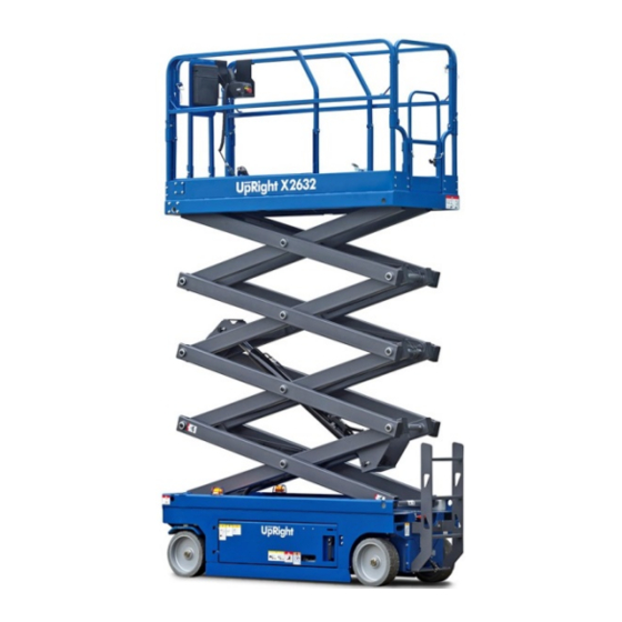
- Page 1 Instant UpRight Self-propelled Scissor Lift MX & X series Service and Maintenance Manual “Translation of the original instruction”...
- Page 2 It has style with excellent operational features. When your machine requires maintenance, only the genuine spare parts should be used as supplied by Upright in order to ensure safety and reliability. Before operating, please read and understand this manual thoroughly! Note: The Company’s products are in continuous improvement, diagrams are...
- Page 3 Table of content Brief Introduction Essentials..............6 Safety Rules General Safety Rules............7 Specification Hydraulic specifications..............14 Hydraulic joint thread torque............15 Regular maintenance procedures Check table A program Check the operating manual and safety manual..........23 Check the logo and label..........23 Perform pre-operation check..........
- Page 4 B-11 Check the oil level in the drive hub..........34 B-12 Replace the hydraulic tank return filter..........34 ..35 B-13 Check that the brake structure is correct.......... Check table C program Test platform overload pressure sensor and platform height sensor (if ..36 equipped)..
-
Page 5: Table Of Contents
Method of removing the steering wheel seat parts..........63 Method of removing the motor..........64 Method of removing the steering cylinder..........64 Method of removing the rod..........65 Fault code B system fault code ............68 Simplified diagram Electrical diagram Electrical schematic of electric drive A system.......... -
Page 6: Essentials
Internal wiring diagram of base control box of hydraulic drive B ..94 system........Hydraulic diagram ......... Hydraulic schematic of X-W Series ..95 Essentials Thank you for choosing and using our machines. We pay attention to the safety of users, which by our endeavors we attempt to achieve it. We believe that as a user and operator of our equipment, and you comply with the following requirements, the use of equipment in the correct manner will ensure a greater level of safety: therefore it is essential that the user... - Page 7 1. Safety Rules Dangerous Failure to follow the instructions and safety rules in this manual may result in death or serious injury. The machine maintenance work shall not be carried out unless the following conditions are met: Maintenance personnel for this machine are trained and qualified. ...
- Page 8 1.1 Safety Rules Note 1.1.1Personnel Safety Indicates the potential emergency hazard condition, if not Any person working on or around the avoided, could result in property machine, beware of all known dangerous damage. operating safety hazards. Personnel safety and continuous safe operation of If necessary, be sure to wear the machine should be the top priority.
- Page 9 1.1.2 Work Place Safety Be sure to keep flame and lit lighted cigarettes away from flammable substances such as battery gas and engine fuel. Place an approved fire extinguisher in an easily accessible area. Be sure to maintain all the tools and work areas for use.
- Page 10 2. Hydraulic Specifications Function Pump Type: Gear pump Displacement Per rotation Velocity at 3000rpm 12L/min Functional Manifold System safety valve pressure 240bar Raise safety valve pressure 190bar Steering relief valve pressure 120bar Steering flow regulator 3.5L/min “Translation of the original instruction”...
-
Page 11: Hydraulic Joint Thread Torque
2.3 Hydraulic Joint Thread Torque Metric O-ring flat seal torque, 74° metric torque “Translation of the original instruction”... - Page 12 2.4 Hydraulic Hoses and Fittings Installation Procedures 1.Replace the "O" ring. 2.When the seal leaks, the "O" ring must be replaced. The "O" ring shall not be reused if the torque at the joint or hose connector exceeds the tightening torque/force of the hand. 3.Apply a layer of oil to the "O"...
- Page 13 2.5 Specification SAE Fastener Torque Chart Use this Chart only for reference unless otherwise noted in other places in this manual. * Dimension Screw thread Class 5 Class 8 A574 High strength black oxidation bolts Lubricant Metric Fasteners Torque Chart Use this Chart only for reference unless otherwise noted in other places in this manual.
- Page 14 “Translation of the original instruction”...
-
Page 15: Regular Maintenance Procedures
After completing a series of steps, an error result Before operating the machine, repair all damage appears and malfunctions of the machine. Use only Instant UpRight approved replacement parts. For machines that are idle for more than 3 months, quarterly checks must be made. - Page 16 personnel. 3.1 Regular Maintenance Procedures Pre-delivery preparation report Maintenance Symbol Legend: Note: This manual uses the following The pre-delivery preparation report symbols to help express the relevant contains a checklist of each type of meaning in the instructions. When the periodic inspection.
- Page 17 3.2 Basic principle The implementation of "pre-delivery" is the responsibility of the dealer. Perform "pre-delivery" inspection before each delivery. The purpose of the inspection is to find out if there is a significant problem before the machine is put into use. Damaged or altered machines should not be used.
- Page 18 Prepare before delivery All Checks before Operating are completed The maintenance project is completed Functional testing is completed Model Series Number Date Machine owner Inspector (please write in block letters) Inspector signature Inspector duties Inspector’s office “Translation of the original instruction”...
- Page 19 4. Maintenance Check Report Model Serial number Date Machine owner Inspector (please write in block letters) Inspector signature Inspector duties Inspector's office Copy this report for use with each check. Select the appropriate checklist according to the type of inspection. Every day or every 8 hours Check: Every quarter or every 250 hours...
-
Page 20: A-2 Check The Logo And Label
Check table A A-1 Check the Operating and safety manual/s Check the logo and label Perform pre-operation check Perform Functional test/ check Check the hydraulic oil level Check for hydraulic oil leak Check the tire pressure & nuts torqued “Translation of the original instruction”... -
Page 21: B-1 Check The Battery
Check Table B Check the battery connections & fluid level Check the electrical wiring Check tyre, wheel and groove nut torque Test emergency stop function Test the key switch function Test drive brakes Test drive speed - stowed position Test drive speed - raised position B-9 Check the electrical contactor B-10 Perform hydraulic oil analysis B-11 Check the oil level in the drive hub... - Page 22 4.After using the manual, return it to the Holder Signs and labels immediately. box. If you need to change the manual, please If you need to change the manual, please contact Instant UpRight or authorised contact Instant UpRight or authorised dealer. dealer. “Translation of the original instruction”...
- Page 23 4.1.4 Perform Functional Tests 4.1.3Perform Pre-operation Check Instant UpRight requires this procedure to be Instant UpRight requires this procedure to be carried out every 8 hours or at minimum daily. carried out every 8 hours or at minimum daily. Completing the functional test is critical to safe Completing the "pre-operation check"...
- Page 24 4.1.6 Check the Hydraulic Oil Leak 4.1.5Check the Hydraulic Oil Level Inspecting hydraulic oil leaks is critical to safe Keeping the hydraulic oil at the right oil level is operation and to maintain good performance of the critical to the machine's work. If the hydraulic oil is machine.
- Page 25 4.1.7 Check the Tire Pressure The risk of physical injury. Excessive tyre pressure may explode and may result in death or serious injury. Danger of tipping. Do not use temporary leak repair methods on tyres to repair the product. Warning! For machines with sponge rubber heart tyres, this check is not required.
- Page 26 4.Allow the battery to fully charge and leave for at least 6 hours. 5.Remove the battery vent cover and check the Instant UpRight specifications require this procedure to specific gravity of each battery unit with a liquid be executed every 250 hours or quarterly, whichever hydrometer.
- Page 27 11.Install the ventilation cover and neutralize any operation of the battery charger, please contact the electrolyte that may overflow. Instant UpRight service department. All models: 12.Check each battery pack and make sure the battery wiring is correct. Please refer to the battery wiring diagram on the machine.
- Page 28 3.Check that all of the harness connectors are coated 4.2.2 Check the Electrical Wiring with an adequate insulating grease layer: Instant UpRight specifications require this procedure to Ground controller be executed every 250 hours or quarterly, whichever Platform controller comes first.
- Page 29 4.2.4 Test Emergency Stop Torque Instant UpRight specifications require this procedure to be executed every 250 hours or quarterly, Instant UpRight specifications require this procedure to whichever comes first. be executed every 250 hours or quarterly, whichever comes first. A functioning emergency stop system is very important for the safe operation of the machine.
- Page 30 4.2.5 Test the Key Switch 4.2.6 Test Drive Brakes Instant UpRight specifications require this procedure to Instant UpRight specifications require this procedure be executed every 250 hours or quarterly, whichever to be executed every 250 hours or quarterly, comes first.
- Page 31 4.2.7 Test Drive Speed - Stowed 4.2.8 Test Drive Speed - Raised Position Position Instant UpRight specifications require this procedure Instant UpRight specifications require this to be executed every 250 hours or quarterly, procedure to be executed every 250 hours or whichever comes first.
- Page 32 B-10 4.2.9 Check the Electrical Contactor 4.2.10 Perform Hydraulic Oil Analysis Instant UpRight specifications require this procedure Instant UpRight specifications require this procedure to be executed every 250 hours or quarterly, to be executed every 250 hours or quarterly, whichever comes first.
- Page 33 B-12 B-11 4.2.12 Replace the Hydraulic Tank 4.2.11 Check the oil level in the Return Filter drive hub Replacing the hydraulic tank oil return filter is If you do not maintain the appropriate drive wheel critical to maintaining the good performance and oil level may lead to poor machine performance, service life of the machine.
- Page 34 B-13 4.2.13 Make Sure the Brake Assembly Mechanism is Correct The brake mechansim is critical to safe operation and to maintain good machine performance. The brake should hold the machine when stopped and allow movement when a drive function is activated. If the brakes cannot function adequately to allow movement they can be adjusted to release the brake and allow the machine be moved for maintenance.
- Page 35 2.Insert the positive pole of the multimeter probe equipped) firmly into the cable rubber sleeve of the pressure Instant UpRight specification requires this procedure to be sensor pin A. See the illustration below. executed every 500 hours or every six months, whichever comes first, or when the machine can not lift the maximum 3.Insert the negative pole of the multimeter probe...
- Page 36 9.Insert the positive pole of the multimeter probe firmly 4.3.3 Platform Height Sensor into the cable rubber sleeve of the pressure sensor pin 15.In the platform height sensor assembly, locate the C. See below for illustrations. end of the platform height along the platform height sensor cable.
- Page 37 18.Insert the positive pole of the multimeter probe 22.Turn the key switch on the ground controller firmly into the cable rubber sleeve of platform height to the OFF position and push the red "emergency sensor pin C. See below for illustrations. stop"...
- Page 38 4.4 Check Table D program 4.4.2 Replace the Hydraulic Filter 4.4.1 Check the Chassis and Instant UpRight specifications require this procedure to Platform Slider be executed every 250 hours or quarterly, whichever comes first. Instant UpRight specifications require this procedure...
- Page 39 2.Apply a thin layer of new oil to the gasket of the new hydraulic filter. 4.4.3 Replace the Wheel Oil 3.Install the new filter and tighten it by hand. Note: The manufacturer-driven hub specification 4.Use the permanent ink marker to write the date and requires this one-time procedure to be executed number of hours displayed on the timer on the 150 hours after the first use.
- Page 40 4.4.4 Test Function Pump Instant UpRight specification requires this procedure to be executed every 1000 hours or annually, whichever comes first. Functional pump operation is normal for safe vibration operation and machine operation are essential. NOTE: This procedure is executed on a rugged, horizontal surface and the platform is in stowed position, when the platform extension table is fully indented.
- Page 41 Remove the ground control 4.5.1 Test or Replace Hydraulic Oil box. Instant UpRight specifications require that this procedure be performed every 2,000 hours or every 4.Find the fuel tank cover. Remove the fuel tank cover two years, whichever comes first.
- Page 42 14.Install the drain plug on the thread with a thread sealant. and Wheel Bearings 15.Install the inlet filter with threaded sealing Instant UpRight specifications require that this material on the threads. procedure be performed every 2,000 hours or every two years, whichever comes first.
- Page 43 16. Install the new bearing grease seal into the hub 6. Remove the dust cover from the hub. Remove the and press evenly until it flush. slotted nuts. 17. Slide the hub onto the operating fork spindle. 7. Tighten the groove nut with a torque of 203 Nm to install the bearing.
- Page 44 5. Repair procedures About this section The repair program must be carried out by personnel Most of the procedures in this section should be trained and qualified for this machine. carried out by trained professional service personnel in well-equipped workplaces. When Damaged or malfunctioning machines should be marked the fault is found, select the appropriate repair immediately and removed from service.
- Page 45 1.Carefully remove the platform controller board fasteners. 5.1.1 Platform Removal 2.Carefully remove the platform controller board Controller Circuit Board Method from the platform control box. 4.Push the red "emergency stop" button of the 3.Remove the transparent cap from the platform ground and platform controller into the OFF controller board and save it.
- Page 46 5.1.3 Method to Remove the Platform 5.1.2 Method to R emove the Handle Alarm 1.Press the red "emergency stop" button on the ground 1.Press the red "emergency stop" button on the and platform controller into the OFF position. ground and platform controller into the OFF position. 2.Disconnect the platform controller from the control 2.Disconnect the platform controller from the control cable on the platform.
- Page 47 5.1.4 Method to remove the platform controller emergency stop button 1.Push the red "emergency stop" button of the ground and platform controller into the OFF position. 2.Disconnect the platform controller from the control cable on the platform. 3.Remove the fasteners that secure the platform control box to the platform controller bracket. 4.Remove the fasteners that secure the bottom cover to the platform control box.
- Page 48 5.2 Platform Components 5.Remove the platform AC power socket cover. Mark and disconnect the wiring on the socket. Warning! Risk of electric shock / burn. Exposure to 5.2.1 Method to Remove the Platform live circuits can result in death or serious injury. Remove all rings, watches and other accessories.
- Page 49 5.2.2 Method to Remove the Platform Extension 1.Lower the platform to the stowed position. 2.Use the lifting strap to support the platform extension. 3.Remove the captive screws as shown. 4.Slowly lift the extension platform and place it on a device that can be used as a support. Warning! Risk of injury.
- Page 50 Scissor arm parts (MX1930 for sample) Steering End Non-steering End 1.Upper arm shaft block 8.Slider 2.80W outside upper arm 9.80W inside upper arm 3.Cylinder upper seat pin 10.Middle arm 3 welding 4.Arm long pin 11.Side arm 5.Middle arm pin 12.Arm seat pin 6.Middle arm 4 assembly 13.Scissor arm welding 7.Arm base pin...
-
Page 51: Lifting Cylinder
Warning! The risk of injury. When 5.2.3 Method of removing arm removing the connecting rod assembly from the machine, if the support is improper, the parts connecting rod assembly will lose balance and fall. The risk of physical injury. The completion of this procedure requires special repair skills, lifting equipment and suitable workshops. - Page 52 13.Remove the positioning fasteners on the arm length pin (label # 4). 20.Carefully lift the connecting rod assembly away from the machine and place it on the device structure that CAUTION: Do not remove the outer opening ring. can support it. 14.Use a soft metal punch to remove the pin and 24.Remove the pin fasteners on the lower arm (label # place it aside.
- Page 53 Separate Link Group: 1.Use the lift device to connect the 4 hook chain to the inner shearing arm, middle shearing arm 3, and 4 at the end of the scissors arm 4 (# 9, # 10, # 6). Warning! The risk of injury. When removing the connecting rod assembly from the machine, if the support is inadequate r, the connecting rod assembly may lose balance and fall.
- Page 54 Scissor arm parts (X2632 for sample) Steering end Non-steering end 1.Upper arm shaft block 8.slider 2.middle arm pin 9.middle arm 1 assembly 3.middle long pin 10.upper arm assembly 4.cylinder upper seat pin 11.middle arm 2 assembly 5.base arm welding 12.side arm 6.middle arm 4 assembly 13.middle arm 3 welding 7.base arm pin...
- Page 55 5.2.4Method of removing arm parts 5.Remove the positioning fasteners on the arm length pin (label # 3). Warning! The risk of physical injury. The CAUTION: Do not remove the outer opening completion of this procedure requires special repair ring. skills, lifting equipment and suitable workshops. 6.Use a soft metal punch to remove the pin and Without these skills and tools, the execution of this place it aside.
- Page 56 13. Remove the positioning fasteners on the 20.Mark and disconnect the harness on the lifting arm length pin (label # 3). cylinder block. 21.Mark and disconnect the hydraulic hoses on the lifting hydraulic cylinder. Plug the hose and cover the CAUTION: Do not remove the outer opening joint with the cover.
- Page 57 5.2.5 Method to Replace the Platform Pad Platform Pad 1.Remove the platform. Please refer to the method of removing the platform. 2.Remove the platform slider and remove the pad. 3.Install the platform pad. Note: When installing the platform, you must drill holes at the bottom and top of the platform pad.
- Page 58 5.2.6 Lifting cylinder Lifting cylinders are single acting hydraulic cylinders. X2047, X2647 uses a lifting cylinder; and X3247, X3947 and X4647 use two lifting cylinders. Each lift cylinder is equipped with a one-way valve to prevent the hydraulic cylinder from moving in the event of a hydraulic pipe failure.
- Page 59 X3247, X3947 and X4647 Warning! Lifting cylinders are single acting hydraulic cylinders. X2047, X2647 uses a lifting cylinder; and X3247, X3947 and X4647 use two lifting cylinders. Each lift cylinder is equipped with a one-way valve to prevent the hydraulic cylinder from moving in the event of a hydraulic pipe failure.
- Page 60 5.3 Chassis Parts 5.3.1.2 Method to Remove the Hydraulic Pump 1.Mark, disconnect and plug the hydraulic hose 5.3.1 Hydraulic Pump on the pump. Cover the pump with the cover. The hydraulic pump is a single stage gear pump. Caution! Risk of physical injury. Sprayed out CAUTION: When removing the hose assembly or of the hydraulic oil may penetrate and burn the connector and reinstalling it, you must replace the...
-
Page 61: Hydraulic Tank
1.Open the hydraulic tank side cover. 2.Remove the drain plug from the hydraulic tank 5.3.2 Hydraulic Tank and drain the oil from the tank thoroughly into The main function of the hydraulic tank is to the appropriate container. cool, clean and degrade the hydraulic oil during operation. - Page 62 Right Steering Seat 5.3.3Method Remove 1.Remove the positioning fasteners on the wheel seat arm b. Steering Wheel Seat Assembly 1.Lock the non-steering wheel and place a jack in the center of the drive chassis of the machine's steering end. 2.Loosen the wheel lugs. Do not remove them. 3.Lifting machine about 5CM.
- Page 63 5.3.5 Method to Remove the Steering 5.3.4 Method to Remove the Motor Cylinder Cati Caution! Risk of damage to parts. Only authorized CAUTION: When removing the hose assembly or dealers can perform motor repair operations. connector and reinstalling it, you must replace the Caution! Risk of damage to parts.
- Page 64 5.3.6Method Remove Steering Rod 1.Refer to Repair Procedure 4-3 for removing the steering wheel assembly. a. 140w Steering cylinder b. Wheel seat arm c. Steering connection plate d.Steering seat plastic cover e. Wheel seat right welding f. Hydraulic motor 2.Remove tie rod c from the steering wheel seat assembly.
- Page 65 Fault Code Before troubleshooting: Read, understand and follow the safety instructions Obey: operating instructions operating instructions. The troubleshooting and repair process must be Make sure that all necessary tools and test performed by trained and qualified personnel who equipment are ready. have been trained in the machine.
- Page 66 About this section After finding the fault, use the flow chart in this section to help professional service personnel identify the cause of the malfunction. To operate in this section, you need to have basic hand tools and some test equipment - voltmeter, ohmmeter, pressure gauge. The terminal positions referred to in this section can be found in the corresponding electrical and hydraulic diagrams provided in the diagram below.
-
Page 67: B System Fault Code
B system fault code Code Fault Probable Reason Problem Solution Internal ECU failure ECU content error, EEPROM is Replace ECU not programmed ECU / platform Control cable error or platform Check the control cable communication failure control failure or platform control The configuration code is The machine configuration code Set the configuration... - Page 68 Series / parallel coil error Coil fault or coil circuit break Check the coil or service line ECU speed output hardware ECU internal hardware error Replace ECU error Right brake coil error Coil fault or coil circuit break Check the coil or service line Left brake coil error Coil fault or coil circuit break...
- Page 69 6.2 System noise and vibration Fault Description Method to repair Oil tank level Low oil level causes cavitation in the tank Add proper amount of clean oil Oil is too high / pump The air in the system reduces the Find out where the air enters oil vacuum efficiency of components and controls.
- Page 70 6.3 System Work Overheating Fault Description Method to Repair Oil tank level The oil in the tank is insufficient to meet Add proper amount of clean oil the cooling requirements of the system Radiator (if installed) The radiator is not sufficient to meet the Check the air flow and temperature cooling requirements of the system through the radiator.
- Page 71 6.4 System Unresponsive Fault Description Method to repair Oil tank level System circuit oil supply is insufficient Add proper amount of clean oil Input control signal Pump receives an error control signal . Make sure that the input signals received in both (handle, current or (MDC- handle is bound or have been directions are correct...
- Page 72 6.5 The System will not Operate in Both Directions Fault Description Method to repair Oil tank level System circuit oil supply is insufficient Add proper amount of clean oil Displacement limiter The displacement limiter is misaligned so Make sure the displacement limiter is set correctly that the servo piston is locked Input control...
- Page 73 6.6 A Certain Direction of the System will not Operate Fault Description Method to repair Input control signal (handle, Pump receives an error control signal . Make sure that the input signals received current or pressure) (MDC- handle is bound or have been both directions correct.
- Page 74 6.8 Electrical Fault Diagnosis Fault Description Method to repair The pump works only in one Control coil failure (EDC) Measure coil resistance, direction resistance value should be 14.20 ohms (24V) or 3.66 ohms (12V) at 20 degrees Celsius (70 degrees Fahrenheit). Replace the coil.
- Page 75 7. Schematic Diagram Obey: The troubleshooting and repair process must be performed by trained and qualified personnel who have been trained in the machine. Damaged or malfunctioning machines should be marked immediately and stop operation. Before operating the machine, repair all the damage and trouble.
- Page 76 7.1Electrical Schematic diagram 7.1.1Electrical Schematic of Electric drive A system Pic.1 (Just reference) “Translation of the original instruction”...
- Page 77 Spare Parts Code Borrow drawing register A System Scissor Lift Explanation Old Drawing Code Drawing Code Signature Date Joystick Height Sensor Overload Sensor Mark Design Drawing echnology Zone Revised Documents Standard Audit Approval Signature Date Applicable models: A system scissors lift instructions Pattern mark Total 1 page Version No.
- Page 78 7.1.2 Electrical Schematic diagram of Electric drive B system Pic.2 “Translation of the original instruction”...
- Page 79 Speed Signal Driving Wheel Enable Signal High Speed Back Forward Electric Drive Motor Right Brake Left Brake Ground Control High Speed Turn Right Turn Left Backward Forward Lower Down Lift Turn Right Turn Left Lift Joystick Mark Design Double Check Check Special Change Content Change person...
- Page 80 7.1.3 Electrical Schematic diagram of hydraulic drive A system “Translation of the original instruction”...
- Page 81 Pic.3(Some same as Pic.1) Power Supply Turn Left Switch Turn Right Switch Enable Switch Joystick High Speed Switch Horn button Drive Lift switch Overload Tilt Alarm Shielding red Shielding blue Yellow Green Height Sensor Overload Sensor Inside the box is the option section Platform Mode Height signal input Pressure signal input...
- Page 82 Platform Emergency Stop Button Red Color Ground Emergency Stop Button Charger contactor Valve Group Horn Main Contactor Totally Page 12 A System Scissor Lift Diagram Qty. “Translation of the original instruction”...
- Page 83 7.1.4 Illustration of electrical components of Hydraulic drive A system “Translation of the original instruction”...
- Page 84 Pic.4(Some same as Pic.1) Contactor Insurance White Line Electric power plug Left side door Pothole guard limit switch Joystick Horn Button Lift button Beeper Joystick Low speed Button Driving button Battery Display Stop button A system controller Flash Up and down switch Key switch Emergency Stop Button Ground control diagram...
-
Page 85: High Current Wiring Diagram Of Hydraulic Drive A System
7.1.5 High Current wiring diagram of Hydraulic drive A system Pic.5(Some same as Pic.1) Page 12 The Third Page A System Scissor Lift Wiring Diagram Qty. “Translation of the original instruction”... -
Page 86: Wiring Diagram Of Hydraulic Drive A System
7.1.6 Wiring diagram of Hydraulic drive A system “Translation of the original instruction”... - Page 87 Pic.6(Some same as Pic.1) 2m stop Lower down Valve Lower down wire, lift switch, 2m stop wiring Charger Batteries Joystick Ground Control Upper 6 core wiring Controller The wiring connected Ground control and Controller Pothole guard switch Pothole guard switch Valve Group Totally 12 pages The fourth Page...
- Page 88 7.1.7Down line, raised switch, 2 m limit six core line diagram of Hydraulic drive A system Pic.7(Some same as Pic.1) Totally 12 pages The fifth Page Lower down wiring, up switch, and 2 m 6 core wiring diagram Qty. “Translation of the original instruction”...
- Page 89 7.1.8 Down line, raised switch, 2 m limit six-wire connection diagram of Hydraulic drive A system “Translation of the original instruction”...
- Page 90 Pic.8(Some same as Pic.1) Male Plug Insurance Female Plug Charger Protection 1 Charger Protection 2 White Black White Black Yellow Blue Brown Orange Insurance Charger Protection 1 Charger Protection 2 Totally 12 Pages The sixth Page Lower down wiring, up switch, and 2 m 6 core wiring diagram Qty.
-
Page 91: Schematic Diagram Of Valve Group Connection Line Of Lower Control Box To Controller Of
7.1.9 Schematic diagram of valve group connection line of lower control box to controller of Hydraulic drive A system Pic.9(Some same as Pic.1) 16 core male plug Totally 12 pages The seventh Page The wiring connected Ground control to controller Qty. - Page 92 7.1.10 Wiring diagram of the valve group connection line of the lower control box to the controller of Hydraulic drive A system Pic.10(Some same as Pic.1) 16 core male plug male plug Female Plug Charger Protection 1 Charger Protection 2 Insurance Totally 12 pages The Eighth Page...
- Page 93 7.1.11Upper control six core diagram of Hydraulic drive A system “Translation of the original instruction”...
- Page 94 Pic.11(Some same as Pic.1) Quick connect Quick connect Line No. Emergency output Line No. Emergency input Line No. Orange Blue Black Brown Yellow Line No. Emergency output Line No. Emergency input Line No. Quick connect 2 Quick connect 2 Totally 12 pages The ninth Page Upper 6 Core Qty.
- Page 95 7.1.12 Base control box internal wiring diagram of Hydraulic drive A system “Translation of the original instruction”...
- Page 96 Pic.12(Some same as Pic.1) Relay Red Line Red Line Red Line Key Switch Red Line Green Line Yellow Line Blue Line Red Line Black Line 16 Core Female Plug Red Line Fast Connect 1 Note: 1. The wiring is 0.75mm2 2.
- Page 97 7.1.13 Upper control box internal wiring diagram of Hydraulic drive A system “Translation of the original instruction”...
- Page 98 Pic.13(Some same as Pic.1) Horn Connect Connect Emergency Stop Button Wiring Fast Connect 1.2 Orange Blue Black Yellow Brown Totally 12 pages The eleventh page Joystick Wiring Qty. “Translation of the original instruction”...
- Page 99 7.1.14 Electrical schematic of Hydraulic drive B system Pic.14(Some same as Pic.1) B System Scissor Lift Platform Control Ground Emergency Stop Key Switch Wiring Key Switch Insurance Ground Control Platform UP/Down Down Main Contactor Batteries Speed Signal Enable Signal “Translation of the original instruction”...
- Page 100 Horn Option Drive motor light indictor Power Relay Horn Pothole Guard Switch 1 Pothole Guard Switch 1 Level switch Level switch power Level switch output Data Data Platform Connecting to Ground Valve Drive Power Negative power Positive Power Overload Limit Switch (Option) Down Limit Switch (Option) Up Limit Switch (Option) Control Power...
- Page 101 7.1.15 Illustration of electrical components of Hydraulic drive B system Pic.15(Some same as Pic.1) “Translation of the original instruction”...
- Page 102 B System Scissor Lift Contactor Insurance Insurance Left Side Door Power Plug Joystick Horn Button Lift Button Beeper Joystick Lower Speed Button Drive Button Battery Display Stop Button B system Electric Drive Motor B System Controller (ECU) Pothole Guard Limit Switch Flash Light Up Switch Key Switch...
-
Page 103: Wiring Diagram Of Hydraulic Drive B System
7.1.16 High current wiring diagram of Hydraulic drive B system Pic.16(Some same as Pic.1) B System Scissor Lift Totally 8 pages The third Page B System Scissor Lift Electric Wiring Diagram Qty. “Translation of the original instruction”... - Page 104 7.1.17Wiring diagram of Hydraulic drive B system “Translation of the original instruction”...
- Page 105 Pic.17(Some same as Pic.1) B System Scissor Lift 6 Core wiring Charger Positive of Charger Negative of Charger Charger Protection Contactor Insurance Insurance Joystick Male Plug light-emitting diode Valve Group Batteries Fast Connect 1.2 Fast Connect 2 Ground Control Fast Connect 1.2 Joystick 6 Core wiring Tilt Switch 16 Core Female Plug...
- Page 106 7.1.18 Upper control six core diagram of Hydraulic drive B system “Translation of the original instruction”...
- Page 107 Pic.18(Some same as Pic.1) B SYSTEM SCISSOR LIFT Fast Connect 1.2 Fast Connect 1.2 Line No. Emergency Stop Output Line No. Emergency Stop Input Line No.: Orange Brown Black Blue Line No. Emergency Stop Output Line No. Emergency Stop Input Line No.: Fast Connect 1.2 Fast Connect 1.2...
- Page 108 7.1.19 Connection diagram of Hydraulic drive B system Pic.19(Some same as Pic.1) B SYSTEM SCISSOR LIFT Connecting 16 Core Male Plug 2m stop Pothole Guard Top Height Limit Totally 8 pages The sixth Page B SYSTEM SCISSOR LIFT Wiring Qty. “Translation of the original instruction”...
- Page 109 7.1.20 Schematic diagram of connection of Hydraulic drive B system “Translation of the original instruction”...
- Page 110 Pic.20(Some same as Pic.1) B SYSTEM SCISSOR LIFT Connect light-emitting diode Top Height Limit 2m Stop Pothole Guard High Speed Forward Turn Left High Speed Backward Turn Right 6 Core Wiring 16 Core Male Plug Totally 8 pages The Seventh Page B System Wiring Diagram Qty, “Translation of the original instruction”...
- Page 111 7.1.21 Base control panel internal wiring diagram of Hydraulic drive B system “Translation of the original instruction”...
- Page 112 Pic.21(Some same as Pic.1) A System Scissor Lift Explanation Relay 16 Core Female Plug Fast Connect 1 Note: 1. All the wiring is 0.75mm2 2. Hour meter has its own Connect Key Switch Hour Meter Toggle Switch Connecting wiring 5 Emergency Stop Button Beeper Totally 8 pages...
- Page 113 7.2 Hydraulic schematic of MX1930, X2632 7.2.1 Hydraulic valve diagram of X Series “Translation of the original instruction”...
- Page 114 “Translation of the original instruction”...
Need help?
Do you have a question about the MX Series and is the answer not in the manual?
Questions and answers