Upright X26N Service & Parts Manual
Work platform
Hide thumbs
Also See for X26N:
- Service & parts manual (166 pages) ,
- Service manual (103 pages) ,
- Operator's manual (24 pages)
Table of Contents
Advertisement
Advertisement
Chapters
Table of Contents

Related Manuals for Upright X26N


Summary of Contents for Upright X26N
- Page 1 POWERED ACCESS X26N WORK PLATFORM 508244-005 sn : 5119+ Feb10...
- Page 3 X26 Narrow English When contacting UpRight for service or parts information, be sure to include the MODEL and SERIAL NUMBER from the equipment Nameplate. Should the nameplate be missing, the SERIAL NUMBER is also stamped on top of the chassis above the front axle pivot.
- Page 5 OREWORD OW TO ANUAL This manual is divided into six sections. NTRODUCTION ECTION General description and machine specifications. PERATION AND PECIFICATION ECTION Information on how to operate the work platform and how to prepare it for operation. AINTENANCE ECTION Preventative maintenance and service information. ROUBLESHOOTING ECTION Causes and solutions to typical problems.
- Page 6 Please understand that these warnings cannot cover all conceivable ways in which service, whether or not recommended by UpRight, might be done, or of the possible hazardous consequences of each conceivable way, nor could UpRight, investigate all such ways.
- Page 7 URPOSE The purpose of this service and parts manual is to provide instructions and illustrations for the operation and maintenance of this work platform manufactured by UpRight. COPE The manual includes procedures for proper operation, maintenance, adjustment, and repair of this product as well as recommended maintenance schedules and troubleshooting.
- Page 8 The platform is raised and lowered by the elevating assembly. The hydraulic pump, driven by the engine, powers the cylinder. Solenoid operated valves control raising and lowering. HASSIS The chassis is a structural frame that supports all the components of the X26N work platform. URPOSE OF QUIPMENT The objective of the work platform is to provide a quickly deployable, self-propelled, variable height work platform to elevate personnel and materials to overhead work areas.
- Page 9 NEVER charge batteries near sparks or open flame. Charging batteries emit explosive hydrogen gas. Modifications to the aerial work platform are prohibited or permissible only at the approval by UpRight. AFTER USE, secure the work platform from unauthorized use by turning the Keyswitch OFF and removing key.
-
Page 10: Table Of Contents
ONTENTS 1. Introduction ............... .3 Special Information . -
Page 11: Introduction
NTRODUCTION NTRODUCTION This manual covers the X26N Work Platform. Figure 1: Manual Storage Information The manual MUST be stored in the box provided in the machine cage, AT ALL TIMES. Read, understand and follow all safety rules and operating instructions before attempting to operate the machine. -
Page 12: General Description
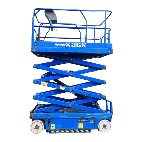
ENERAL ESCRIPTION ENERAL ESCRIPTION D A N G E R DO NOT use the machine if all guardrails are not properly in place and secured. Figure 2: X26 Narrow 1. Platform Controls 2. Manual Case 3. Platform Extension 4. Platform 5. -
Page 13: Special Limitations
PECIAL IMITATIONS PECIAL IMITATIONS PECIAL IMITATIONS D A N G E R D A G E R Travel with the platform raised is limited to creep speed range. Elevating the Work Platform is limited to firm, level surfaces ONLY. D A N G E R A N G E R The elevating function shall ONLY be used when the work platform is level, and on a firm surface. -
Page 14: Controls And Indicators
ONTROLS AND NDICATORS ONTROLS AND NDICATORS The operator shall know the location of each control and indicator and have a thorough knowledge of the function and operation of each before attempting to operate the unit. Figure 3: Controls and Indicators Platform Controls 1 Drive Selectors 2. -
Page 15: Pre-Operation Safety Inspection
7. Inspect the machine thoroughly for cracked welds, loose or missing hardware, hydraulic leaks, damaged cables or hoses, loose wire connections and wheel bolts. Note X26N operates in Maximum Wind conditions equivalent to Beaufort 4 TABLE OF WIND SPEED/VELOCITY BEAUFORT CONDITIONS 3 -7... -
Page 16: System Function Inspection
YSTEM UNCTION NSPECTION YSTEM UNCTION NSPECTION NOTE: Refer to Figure 3 for the locations of various controls and indicators. W A R N I N G STAND CLEAR of the work platform while performing the following checks. Before operating the work platform, survey the work area for surface hazards such as holes, drop-offs, bumps and debris. -
Page 17: Operation
PERATION PERATION Before operating the work platform, ensure that the Pre-Operation Safety Inspection and System Function Inspection have been completed and that any deficiencies have been corrected. NOTE: Never operate a damaged or malfunctioning machine. The operator must be thoroughly trained on this machine. L A T F O R M X T E N S I O N Figure 4: Platform Extension... -
Page 18: Elevating The Platform
PERATION LEVATING THE LATFORM 1. Locate a firm, level surface. 2. Select LIFT mode. 3. While engaging the Interlock Switch, push the Control Handle FORWARD. 4. If the machine is not level the level sensor alarm will sound and the machine will not lift or drive. 5. -
Page 19: Guardrails
PERATION UARDRAILS Figure 6: Guardrails The guardrails may be lowered for the 1. Platform Extension purpose of passing through a standard 2. Platform Controls 3. Platform Extension Retaining Pins doorway. 4. Side-rail Retaining Pins Guardrails must be returned to proper 5. -
Page 20: Parking Brake Release
PERATION ARKING RAKE ELEASE Perform the following only when the machine will not operate under its own power and it is necessary to move the machine or when winching onto a transport vehicle (see “Transporting the Machine”). W A R N I N G NEVER winch or move the machine faster than 0,3 m/sec. -
Page 21: Transporting The Machine
RANSPORTING THE ACHINE RANSPORTING THE ACHINE Always use a transport vehicle when moving a machine to a work site. Towing the machine over long distances will damage the machine and void the warranty. I F T I N G R A N E Figure 8: Secure Crane Straps D A N G E R See specifications for the weight of the machine... -
Page 22: Driving Or Winching Onto A Truck Or Trailer
RANSPORTING THE ACHINE RIVING OR INCHING ONTO A RUCK OR RAILER W A R N I N G Never winch faster than 0,3 m/sec. (1 ft./sec.). Never operate the machine with the parking brakes released. Serious injury or damage could result. 1. -
Page 23: Maintenance
AINTENANCE AINTENANCE W A R N I N G Never perform service while the platform is elevated without first blocking the elevating assembly. DO NOT stand in the elevating assembly area while deploying or storing the brace. L O C K I N G L E V A T I N G S S E M B L Y Figure 9: Scissor Brace... -
Page 24: Level Sensor
AINTENANCE EVEL ENSOR W A R N I N G Never perform service while the platform is elevated without first blocking the elevating assembly. DO NOT stand in the elevating assembly area while deploying or storing the brace. The Level Sensor Is located on the chassis between the scissor sections and is covered with a protective metal box. -
Page 25: Battery Maintenance
Always wear safety glasses when working near batteries. Battery fluid is highly corrosive. Thoroughly rinse away any spilled fluid with clean water. Always replace batteries with UpRight batteries or manufacturer approved replacements weighing 30 kg (66 lbs.) each. • Check the battery fluid level daily, especially if the machine is being used in a warm, dry climate. -
Page 26: Daily Inspection And Maintenance Schedule
AILY NSPECTION AND AINTENANCE CHEDULE AILY NSPECTION AND AINTENANCE CHEDULE The Complete Inspection consists of periodic visual and operational checks, along with periodic minor adjustments that assure proper performance. Daily inspection will prevent abnormal wear and prolong the life of all systems. Perform the inspection and maintenance items daily. Inspection and maintenance shall be performed by personnel who are trained and familiar with mechanical and electrical procedures. -
Page 27: Specifications
11 S PECIFICATIONS 11 S PECIFICATIONS ITEM X26N Platform Size Platform Extension In 0,71 m x 2,21 m [28 in. x 87 in.] 0,71 m x 3,20 m [28 in. x 126 in.] Platform Extension Out Max. Platform Capacity 340 kg [750 lbs.]... - Page 28 X26N 508669-000 x2 508661-000 x2 067195-001 066556-900 067195-001 101210-000 066561-900 101210-000 066561-900 26.3 kg+ 062562-951 THIS PLATFORM IS NOT INSULATED. DIESE ARBEITSBÜHNE IST NICHT ISOLIERT. CETTE PLATEFORME N'EST PAS ISOLEE. 100102-900 503724-000 100102-900 501453-000 501453-000 010076-901 100076-901 014222-903 014222-903 MAX = 340 kg...
- Page 29 llustraIted arts Ce d eCals Control Module Front Panel Upper Control Box Access/Rear View Battery Module Page 2-21...
- Page 30 11 S PECIFICATIONS Page 2 - 20...
- Page 31 This section contains instructions for the maintenance of the Work Platform. Refer to the General Information section for information relevant to all UpRight work platforms. Referring to the Operator Manual will aid in understanding the operation and function of the various com- ponents and systems of the work platform, and help in diagnosing and repair of the machine.
- Page 32 Section 3 - Service & Repair ABLE OF ONTENTS 3-1 Supporting Elevating Assembly ........... 3-3 Installation .
-
Page 33: Supporting Elevating Assembly
Section 3 - Service & Repair Supporting Elevating Assembly 3-1 S UPPORTING LEVATING SSEMBLY W A R N I N G Never perform service on the work platform in the elevating assembly area while platform is elevated without first blocking the elevating assembly. DO NOT stand in elevating assembly area while deploying or storing brace. -
Page 34: Preventative Maintenance
t s i & 3-3 P REVENTATIVE AINTENANCE HECK REVENTATIVE AINTENANCE REVENTATIVE AINTENANCE EPORT Interval Date: _______________________________________ Daily=each shift or every day Owner:______________________________________ 50h/30d=every 50 hours or 30 days 250h/6m=every 250 hours or 6 months Model No: ___________________________________ 1000h/2y=every 1000 hours or 2 years Serial No: ___________________________________ Y=Yes/Acceptable N=No/Not Acceptable... -
Page 35: Parts Location
Section 3 - Service & Repair Parts Location 3-4 P ARTS OCATION Figure 3-2: Parts Location 1. Entry Gate 2. Deck Lock Assembly 3. Work Platform 4. Fold Down Guardrails 5. Platform Extension 6. Platform Controls 7. Rear Guardrail Retaining Pin 8. -
Page 36: General Lubrication
Battery fluid is highly corrosive. Thoroughly rinse away any spilled fluid with clean water. Always replace batteries with UpRight batteries or manufacturer approved replacements. Before disconnecting the battery negative (-) lead, make sure all switches are OFF. If ON, a spark will occur at the ground terminal which could cause an explosion if hydrogen gas or fuel vapors are present. -
Page 37: Batteries
Section 3 - Service & Repair Batteries A T T E R Y A I N T E N A N C E Refer to the Operation Manual included in this Service Manual for specific maintenance and charging instructions. NOTE: If system voltage drops below 17 volts (on a 24 volt system), the charger will not recharge the batteries. If this extreme voltage drop occurs, disconnect and recharge each battery separately using a 6 volt charger to bring the voltage in each up to at least 4 1/2 volts. -
Page 38: Safety Ancillary Equipment
Safety Ancillary Equipment Section 3 - Service & Repair 3-7 S AFETY NCILLARY QUIPMENT R O X I M I T Y W I T C H Figure 3-6: Proximity Switch The Proximity Switch cuts power to the High Speed Drive when the platform is elevated. -
Page 39: Hydraulics
Section 3 - Service & Repair Hydraulics 3-8 H YDRAULICS Y D R A U L I C A N K A N D I L T E R LUID EVEL Figure 3-9: Hydraulic Tank Check the fluid level daily. With the platform fully lowered, open the control module and remove the reservoir breather/cap. -
Page 40: Hydraulic Pump
Hydraulics Section 3 - Service & Repair Y D R A U L I C U M P The Hydraulic Pump is located in the Power Module, and is mounted on the rear of the motor. EMOVAL NOTE: If the hydraulic tank has not been drained, suitable means for plugging the hoses should be provided to prevent excessive fluid loss. -
Page 41: Main Hydraulic Manifold
Section 3 - Service & Repair Hydraulics A I N Y D R A U L I C A N I F O L D Though it is not necessary to remove the manifold to perform all maintenance procedures, a determination should be made prior to beginning as to whether or not the manifold should be removed before mainte- nance procedures begin. - Page 42 Hydraulics Section 3 - Service & Repair ELIEF ALVE Figure 3-13: Hydraulic Manifold with Valves 1. Operate the hydraulic system 10 to 15 minutes to warm the oil. 2. Remove the cap or loosen the locknut on MAIN RELIEF VALVE CHECK VALVE (POTHOLE) the Main Relief Valve.
-
Page 43: Cylinders
Section 3 - Service & Repair Cylinders 3-9 C YLINDERS E P R E S S I O N Y L I N D E R Figure 3-14: Depression Cylinder EMOVAL 1. Mark and disconnect the hose assemblies from the cylinder fittings and immediately cap the openings to prevent foreign material from entering. -
Page 44: Steering Cylinder
Cylinders Section 3 - Service & Repair T E E R I N G Y L I N D E R EMOVAL Figure 3-15: Steering Cylinder Mount Assemblt 1. Mark and disconnect the hose assemblies from the cylinder fittings and immediately cap the openings to prevent foreign material from entering. -
Page 45: Lift Cylinder
Section 3 - Service & Repair Cylinders I F T Y L I N D E R EMOVAL Figure 3-17: Lift Cyminder Assembly 1. Provide a suitable container to catch the hydraulic fluid, then disconnect the hydraulic hoses. Immediately plug hoses to prevent foreign material from entering. -
Page 46: Drive Motors
Drive Motors Section 3 - Service & Repair 3-10 D RIVE OTORS EMOVAL 1. Use a 1000Kg (one ton) capacity jack to raise the front of the machine. Position blocks under the machine to prevent the work platform from falling if the jack fails. 2. -
Page 47: Controls
Section 3 - Service & Repair Controls 3-11 C ONTROLS L A T F O R M O N T R O L S The Proportional Controller can be disassembled to replace defective switches. See the Parts Manual for replacement part numbers. Figure 3-19: Platform Control Box 1. -
Page 48: Chassis Controls
Controls Section 3 - Service & Repair H A S S I S O N T R O L S Figure 3-20: Lower Control Box The chassis control assembly is mounted on the inside of the chassis door, to the left of the Hydraulic tank. 1. - Page 49 Section 3 - Service & Repair 508244-002 Page3-19...
- Page 50 PECIFICATIONS YDRAULIC OMPONENTS NOTE: Always lubricate threads with clean hydraulic oil prior to installation Use the following values to torque hydraulic components used on UpRight Work Platforms. Table : Torque Specifications for Hydraulic Components Type: SAE Part Series Cartridge Poppet...
- Page 51 Maintenance Table : Torque Specifications for Metric Fasteners, U.S. Customary Units 12.9 10.9 Grade 12.9 Grade 10.9 Grade 8.8 Nominal Tightening Torque Tightening Torque Tightening Torque Clamp Clamp Clamp Thread Load Load Load K = .15 K = .20 K = .15 K = .20 K = .15 K = .20...
- Page 52 Section 3 - Service & Repair Page 3-22 508244-002...
- Page 53 Section 4 ROUBLESHOOTING 4.1 I NTRODUCTION The following section on troubleshooting provides guidelines on the types of problems users may encounter in the field, helps determine the cause of problems, and suggests proper corrective action. Careful inspection and accurate analysis of the symptoms listed in the Troubleshooting Guide will localize the trouble more quickly than any other method.
- Page 54 Troubleshooting 4.2 - Troubleshooting 4.2 T ROUBLESHOOTING 1. Verify your problem. • Do a full function test from both the platform and chassis controls, and note all func- tions that are not operating correctly. 2. Narrow the possible causes of the malfunction. •...
- Page 55 4.3 - Troubleshooting Guide 4.3 T ROUBLESHOOTING UIDE TROUBLE PROBABLE CAUSE REMEDY All functions 1. Blown electric motor fuse Check 160 amp electric motor fuse. Replace if blown. inoperable, electric motor 2. Faulty battery Check the voltage output of the battery charger. If less than 24 VDC, does not start.
- Page 56 Fault Codes introduction AULT ODES INTRODUCTION The X-Series is equipped with a fault detection system, if you have a faulty component, bad electrical connection or start up error a fault code will be displayed on the read out located on the upper control box. For fault codes 01 - 39 the following procedure should be followed.
- Page 57 4.5 - Fault Codes 4.5 F AULT ODES 01 – System initialization error 02 – System communication error 22 – Platform Left Turn Switch ON at power-up 23 – Platform Right Turn Switch ON at power-up 25 – Platform Hi-Drive Switch ON at power-up 27 –...
- Page 58 4-6 - Electric 4-6 E LECTRIC Table 4-1: Electrical Troubleshooting Table Component Alarm Batteries Battery Charger 5 AMP Circuit Breaker 175 AMP Fuse Motor Control Motor Chassis Emergency Stop Switch Chassis Key Switch Platform Emergency Stop Switch Interlock Switch PQ Control Handle Height Limit Switch Platform Steering Switch Tilt Sensor...
- Page 59 4-7 - Hydraulic 4-7 H YDRAULIC Table 4-2: Hydraulic Troubleshooting Table Component Check Valve Steering Cylinder Lift Cylinder Depression Mechanism Cylinder Brake Cylinder Suction Strainer Return Filter Drive Motors (2) Pump Main Relief Valve Steering Relief Valve Lift Relief Valve Tank Steering Right/Left Valve Lift Valve...
- Page 60 4-7 - Hydraulic Notes : Page 4-8...
- Page 61 Section 5 CHEMATICS 5.1 I NTRODUCTION This section contains electrical and hydraulic power schematics and associated information for maintenance purposes. The diagrams are to be used in conjunction with the information in Section 4. They allow understanding of the makeup and functions of the systems for checking, tracing, and faultfinding during troubleshooting analysis. ONTENTS Electrical Schematic .
- Page 62 Schematics 5.2 E LECTRIC Hydraulic Schematic Page 5-2 508244-002...
- Page 63 Schematics 5.3 C ABLE SSEMBLY 508244-002 Page 5-3...
- Page 64 Schematics 5.4 J1 C ABLE CHEMATIC Page 5-4 508244-002...
- Page 65 Schematics 5.5 O VERLOAD CHEMATIC 508244-002 Page 5-5...
- Page 66 Schematics 5.6 Hydraulic Schematic Page 5-6 508244-002...
- Page 67 Schematics 508244-002 Page 5-7...
- Page 69 This section lists and illustrates the replaceable assemblies and parts of the X26N Work Platform as manufactured by UpRight Powered Access. Each parts list contains the component parts for that assembly indented to show relationship where applicable. Sec6:1...
- Page 70 Item Part Description Qty. Item Part Description Qty. 066309-011 POWER MODULE 504348-000 LOWER CONTROL ASSY 066310-026 CONTROL MODULE 065943-102 WIRE HARNESS ASSY J3 069199-001 CHARGER 066623-020 LIFT OVERLOAD ALARM 501425-000 SWITCH - PROXIMITY 504160-001 LOWERING CABLE 010076-000 MANUAL CASE 505566-001 LEVEL SENSOR 101182-008 CABLE ASSY W/ CONNECTOR...
- Page 71 Sec6:3...
- Page 72 Item Part Description Qty. Item Part Description Qty. 505042-000 BEARING 504153-001 PIN 5/8 504144-001 BEARING 066159-001 L/H STEERING LINK 504148-001 STEERING CYINDER 504150-000 BEARING 114055-002 MOTOR - HYDRAULIC 114057-000 L/H STEERING ANGLE 502170-000 WHEEL & TYRE 114058-000 R/H STEERING ANGLE 066869-000 CHASSIS 066313-001...
- Page 73 Item Part Description Qty. Item Part Description Qty. 502152-000 COTTER PIN 504151-000 VALVE ASSEMBLY 062642-001 BEARING GARLOCK 10DU12 066865-100 COUNTERWEIGHT - R-BULKHD 066866-000 COUNTERWEIGHT CASTING 058819-000 M6 GREASE NIPPLE 502097-000 FLAT WASHER ASTM 504154-000 PIN - BELL CRANK 504157-001 CUP BEARING With Seal 503673-000 BUSH 12DU08 504157-000...
- Page 74 Item Part Description Qty. Item Part Description Qty. 504001-011 CHASSIS ASSEMBLY 066183-001 BEARING EAGLE PICHER #323632 114200-001 SCISSOR ASSEMBLY 504186-000 MOUNTING PIN 504003-011 PLATFORM WELDMENT 504186-003 MOUNTING PIN 066189-000 WEAR PAD 1/4 504125-000 SLIDE BLOCK 066189-001 WEAR PAD 3/8 066189-004 WEAR PAD 1/8 504125-003 SLIDE BLOCK (BOTTOM)
- Page 75 Sec6:7...
- Page 76 114200-001 Item Part Description Qty. 066183-001 BEARING, OILITE #EP3236-24 504129-001 LIFT CYLINDER (504129-002 - ANSI) 504129-010 SEAL KIT, LIFT CYLINDER 504104-000 WELDMENT, MID INNER TUBE 1/8 114201-002 WELDMENT, TOP/BOTOM OUTER 114202-001 WELDMENT, BOTTOM INNER 3/16 504103-000 WELDMENT, MID OUTER 1/4 504122-003 WELDMENT, PIVOT PIN 504122-001...
- Page 77 Sec6:9...
- Page 78 Sec6:10...
- Page 79 Item Part Description Qty. 504108-002 SCISSOR WELDMENT - INNER, CYLINER 504122-003 PIVOT PIN - STANDARD LONG 504120-000 FLANGED BUSHING, 50mm 057048-000 GREASE NIPPLE, M6 504187-000 PIN LOCK PLATE 504122-001 PIVOT PIN - STANDARD, MEDIUM 504123-000 PIVOT PIN - CYLINDER ROD 504120-001 PLAIN BUSH, 50mm 504189-001...
- Page 80 Item Part Description Qty. Item Part Description Qty. 066480-000 GATE 505300-010 SWING BAR 066497-026 WELDMENT, GATE KICKRAIL 502204-001 TORSION SPRING 066441-000 PIVOT, GATE 027899-000 U BOLT 505300-017 WELDMENT UPPER R/H 066519-000 WELDMENT, GATE HINGE 505300-012 GUARDRAIL MID 505300-015 WELDMENT UPPER L/H Sec6:12...
- Page 81 Item Part Description Qty. Item Part Description Qty. 066251-026 WELDMENT DECK EXT. 505300-010 EX-DECK UPPER L/H RAIL 502148-000 WEAR PAD 505300-008 EX-DECK UPPER R/H RAIL 502129-000 STOP 505300-000 EX-DECK LOWER RAIL 502131-000 WEAR PAD 003570-005 PULL PIN WITH KEY RING 502097-000 WASHER SAE 1 1/4 PLATED 504138-000...
- Page 82 Item Part Description Qty. Item Part Description Qty. 504128-001 HYDRAULIC TANK 066735-001 WELDMENT, POTHOLE 062791-002 LATCH 503800-001 MAIN MANIFOLD BLOCK 502588-000 ALARM 504536-000 PUMP ASSEMBLY 502489-000 LINE CONTACTOR 504133-000 BRACKET, GUIDE PAD ANGLE 510066-000 MAIN FUSE 504134-000 GUIDE PAD 510065-000 MOUNTING PLATE, FUSE 502152-000 SPLIT PIN...
- Page 83 Item Part Description Qty. Item Part Description Qty. 501074-000 BATTERY 504135-000 BUSHING, POTHOLE PIVOT 066309-011 WELDMENT, DOOR MODULE 504153-001 PIVOT PIN, POTHOLE 062791-002 LATCH 504134-000 GUIDE PAD 066735-001 WELDMENT, POTHOLE 504126-000 BUSHING, MODULE PIVOT 504133-000 BRACKET, GUIDE PAD ANGLE 502152-000 SPLIT PIN 066713-002 HINGE...
- Page 84 503800-001 Item Part Description Qty. TEST PORT 058358-000 FITTING, 1/4” - 1/4” MALE/MALE 057122-000 FITTING, 3/8” - 3/8” MALE/MALE 057377-000 FITTING, 1/2” - 1/2” (MALE/MALE) 503803-000 CROSS LINE RELIEF VALVE (DRIVE) 503804-000 VALVE, SOLENOID (DRIVE) 503805-000 VALVE, SOLENOID (DRIVE/LIFT) 503807-000 PRESSURE RELIEF (MAIN LIFT) 503808-000 VALVE, SOLENOID (STEERING)
- Page 85 Part Description Qty. Part Description Qty. 504148-011 SEAL KIT 504132-010 SEAL KIT (ANSI 504129-002 ) Item Part Description Qty. 058819-000 M6 GREASE NIPPLE 504120-000 FLANGED BUSHING 504129-011 SEAL KIT Sec6:17...
- Page 86 Item Part Description Qty. 504141-001 COVER, LOWER CONTROL BOX 504142-000 BOX, LOWER CONTROL BOX 501867-000 EMERGENCY STOP BUTTON 502251-000 TOGGLE SWITCH 502250-000 ENABLE BUTTON 501866-000 501866-001 KEY SWITCH Sec6:18...
- Page 87 Item Part Description Qty. 501867-000 EMERGENCY STOP BUTTON 501882-002 RUBBER BOOT, STEERING 501882-000 JOYSTICK 501882-001 RUBBER BOOT, JOYSTICK 502486-000 DECAL 501592-000 MOUNTING PLATE 502591-000 SEAL 502453-000 CIRCUIT BOARD 502587-001 SOCKET, MAIN HARNESS 502605-000 SOCKET, OVERLOAD 502496-000 UCB, BOX ONLY Sec6:19...
- Page 88 Sec6:20...
- Page 89 Item Part Description Qty. 502483-000 502531-000 J1 HARNESS 503800-001 MAIN MANIFOLD BLOCK 504349-000 UPPER CONTROLS 505006-000 LOWER CONTROLS 505566-001 TILT SENSOR 501868-000 HORN 502588-000 ALARM 505072-000 PROXIMITY SENSOR 502494-000 FUSE 058937-000 BATTERY DISCONNECT PLUG 502594-000 HARNESS, BATTERY DISCONNECT - BATT (-) 502595-000 HARNESS, BATTERY DISCONNECT - BATT (+) 501074-000...
- Page 90 Sec6:22...
- Page 91 Item Part Description Qty. 509420-000 HYDRAULIC HOSE, BLOCK - SERIES/PARA BLOCK 509421-000 HYDRAULIC HOSE, BLOCK D2 - SERIES/PARA D2 509416-000 HYDRAULIC HOSE,SERIES/PARA BLOCK - MOTORS 509417-000 HYDRAULIC HOSE, BLOCK - BRAKE TEE 509422-000 HYDRAULIC HOSE, BRAKE TEE - MOTORS 509423-000 HYDRAULIC HOSE, BLOCK - STEERING CYLINDER 509424-000 HYDRAULIC HOSE, BLOCK - POTHOLE TEE...
- Page 92 Item Part Description Qty. 503950-001 MOUNTING PLATE, ELECTRICAL BOX 504561-002 MOUNTING PLATE, CIRCUIT BOARD 504558-000 CIRCUIT BOARD 504560-000 PRESSURE TRANSDUCER 504559-000 ANGLE TRANSDUCER...
- Page 93 Sec6:25...
- Page 94 llustraIted arts Ce d eCals Control Module Front Panel Upper Control Box Access/Rear View Battery Module Sec6:26...
- Page 95 X26N 508669-000 x2 508661-000 x2 067195-001 066556-900 067195-001 101210-000 066561-900 101210-000 066561-900 26.3 kg+ 062562-951 THIS PLATFORM IS NOT INSULATED. DIESE ARBEITSBÜHNE IST NICHT ISOLIERT. CETTE PLATEFORME N'EST PAS ISOLEE. 100102-900 503724-000 100102-900 501453-000 501453-000 010076-901 100076-901 014222-903 014222-903 MAX = 340 kg...
- Page 96 llustraIted arts Ce d eCals Control Module 5 29 Front Panel Upper Control Box Access/Rear View in 3 positions Battery Module Sec6:27...
- Page 97 X26N 508667-000 Collision Hazard Impact from decending platform may cause injury, stand clear 066556-900 066556-000 508661-000 Qty. 2 067195-001 066550-000 DANGER WARNING Explosive gas is generated when charging batteries DO NOT expose to sparks or flames. 066561-900 101251-000 066552-000 066561-900...
- Page 98 Sec6-30...
- Page 100 Local Distributor: Lokaler Vertiebshändler: Distributeur local: El Distribuidor local: Il Distributore locale: Europe TEL: +1 (559) 443 6600 TEL: +44 (0) 845 1550 058 FAX: +1 (559) 268 2433 www.upright.com...
Need help?
Do you have a question about the X26N and is the answer not in the manual?
Questions and answers