Sign In
Upload
Manuals
Brands
Upright Manuals
Lifting Systems
X26N
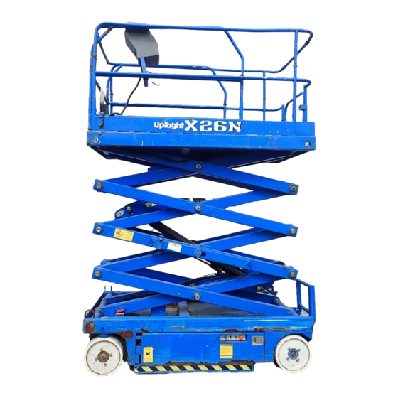
Upright X26N Manuals
Manuals and User Guides for Upright X26N. We have
6
Upright X26N manuals available for free PDF download: Service & Parts Manual, Service Manual, Operator's Manual
Upright X26N Service & Parts Manual (164 pages)
Work Platforms
Brand:
Upright
| Category:
Lifting Systems
| Size: 9.55 MB
Table of Contents
Table of Contents
5
Introduction
11
Purpose
11
Scope
11
General Description
11
Platform
11
Platform Controller
11
Elevating Assembly
11
Figure 1-1: X Series Work Platform
11
Chassis
12
Purpose of Equipment
12
Operation and Specifications
14
Introduction
14
Pre-Operation and Safety Inspection
14
Operation and Specifications
15
Figure 2-2: Emergency Lowering
15
Operation
16
Platform Extension
16
Travel with Platform Lowered
16
Figure 2-4: Platform Extension
16
Steering
17
Elevating the Platform
17
Travel with Work Platform Elevated
17
Lowering the Platform
17
Emergency Lowering
18
Figure 2-5: Emergency Lowering Valve Handle
18
Lower the Guardrails, X26N
19
Fold down Guardrails, X31N
19
After Use each Day
20
Parking Brake Release
20
Figure 2-6: Parking Brake Release
20
2.4 - Transporting the Work Platform
21
Figure 2-7: Secure Crane Straps
21
Figure 2-8: Transporting the Work Platform
21
Maintenance
22
Blocking Elevating Assembly
22
Figure 2-9: Blocking the Elevating Assembly
22
Battery Maintenance
23
Figure 2-10: Power Module
23
Battery Charging
24
Preventative Maintenance
26
2.7 - Preventative Maintenance Checklist Maintenance Checklist
27
Preventative Maintenance Key
27
Preventative Maintenance Report
27
Specifications
28
Maintenance
29
Introduction
29
Terminology
29
General Procedures
29
Date Code Identification on Hoses
29
Special Tools
30
Upright Connectors
30
Figure 3-1: Upright Connector Kit
30
Figure 3-2: Plugs and Receptacles, Upright Connectors
30
Crimping
31
Female Connector (Receptacle)
31
Figure 3-3: Locking Finger, Upright Connector
31
Figure 3-4: Heavy Duty Upright Connector
31
Releasing Locking Fingers
31
Removing Contact from Heavy Duty Plug
31
Supporting Elevating Assembly
32
X20N, X20W, X26N
32
Figure 3-5: Blocking the Elevating Assembly--X20N, X20W, X26N
32
X31N
33
Battery Maintenance
34
Battery Inspection and Cleaning
34
Battery Charging
34
Battery Cell Equalization
35
Switch Adjustments
36
Tilt Sensor
36
Down Limit Switch
36
Figure 3-9: Level Sensor
36
Figure 3-10: down Limit Switch
36
Control Handle
37
Figure 3-11: Control Handle
37
3.8 - Motor Controller and I/O Board Dip Switch Settings
38
Controller
38
I/O Board
38
Figure 3-12: Controller
38
Figure 3-13: I/O Board
38
3.9 - Hydraulic Oil Tank and Filter
39
Reservoir Breather/Cap
39
Figure 3-14: Oil Filter
39
Figure 3-15: Hydraulic Tank
39
3.10 - Setting Hydraulic Pressures
40
Main Relief Valve
40
Steering Relief Valve
41
Lift Relief Valve
41
Counterbalance Valves
41
Hydraulic Manifold
42
Removal
42
Disassembly
42
Cleaning and Inspection
42
Assembly
42
Installation
42
Figure 3-17: Hydraulic Manifold
43
Hydraulic Pump
44
Removal
44
Installation
44
Hydraulic Drive Motors and Hubs
44
Figure 3-18: Hydraulic Pump
44
Figure 3-19: Drive Motor
44
Brake Cylinder
45
Removal
45
Disassembly
45
Figure 3-21: Brake Cylinder Assembly
45
Cleaning and Inspection
46
Assembly
46
Installation
46
3.15 - Steering Cylinder
46
Removal
46
Disassembly
46
Assembly
47
Installation
47
3.16 - Depression Mechanism Cylinder
47
Removal
47
Figure 3-23: Depression Mechanism Cylinder
47
Removal
48
Disassembly
48
Cleaning and Inspection
48
Figure 3-24: Five Section Scissor Assembly
48
Reassembly
49
Figure 3-25: Lift Cylinder Remove and Replace
49
Installation
50
Figure 3-26: Lift Cylinder Assembly
50
Electric Motor
51
Troubleshooting
51
Disassembly
51
Inspection
51
Figure 3-27: Electric Motor
51
Maintenance
52
3.19 - Torque Specifications
52
Fasteners
52
Table 3-1: Torque Specifications for Hydraulic Components
52
Table 3-2: Torque Specifications for SAE Fasteners
52
Table 3-3: Torque Specifications for Metric Fasteners, U.S. Customary Units
53
Table 3-4: Torque Specifications for Metric Fasteners, si Units
53
Introduction
55
General Procedure
55
Troubleshooting
56
Special Tools
56
Adjustment Procedures
56
Checking Pump Pressures
56
4.3 - Upright Motor Controller Diagnostics
57
Table 4-1: LED Fault Codes
57
Measured Voltage at I/O Board
58
Hydraulic
59
Troubleshooting
59
Table 4-2: Hydraulic Troubleshooting Table
59
Electric
60
Figure 2-11: Battery Charger
60
Figure 3-7: Battery Charger
60
Table 4-3: Electrical Troubleshooting Table
60
Introduction
63
Contents
63
Electrical
64
Figure 2-1: Chassis Controls
64
Figure 2-3: Platform Controls
64
Legend: Electrical Schematic, X20N--065616-024
64
Legend: Electrical Schematic, X20W, X26N, X31N--066769-020
66
Legend: Hydraulic Schematic, X20N--065615-023
68
Legend: Hydraulic Schematic, X20W, X26N--066781-020
70
Legend: Hydraulic Schematic, X31N--066781-021
72
Hydraulics
80
Figure 3-8: Power Module
84
Figure 3-20: Brake Cylinder
100
Figure 3-22: Steering Cylinder
100
Lift Cylinder
112
Figure 3-16: Hydraulic Manifold
128
Advertisement
Upright X26N Service & Parts Manual (166 pages)
Aerial Work Platform
Brand:
Upright
| Category:
Lifting Systems
| Size: 6.22 MB
Table of Contents
Table of Contents
5
Introduction & Specifications
7
Introduction
7
Purpose
7
Scope
7
General Information
7
Description
7
Purpose and Limitations
7
Specifications
8
Machine Preparation
9
Preparation for Use
9
Preparation for Shipment
9
Transporting Work Platform
10
Storage
10
Preservation
10
Batteries
10
Operation
11
Introduction
11
General Functioning
11
Design Features
11
Safety Rules and Precautions
11
Controls and Indicators
12
Platform/Controller
12
Chassis
12
Battery Charger
13
Pre-Operation Inspection
14
Operation
14
Travel with Platform Lowered
15
Steering
15
Elevating Platform
15
Travel with Platform Elevated
15
Lowering Platform
16
Emergency Lowering
16
After Use each Day
16
Parking Brake Release
16
Fold down Guardrails
16
Maintenance
17
Introduction
17
Special Tools
17
Preventative Maintenance
17
Preventative Maintenance Table Key
18
Preventative Maintenance Report
18
Blocking Elevating Assembly
19
Installation
19
Removal
19
Blocking the Elevating Assembly
19
Battery Maintenance
20
Battery Charging
20
Battery Inspection and Cleaning
20
Battery Cell Equalization
21
Lubrication
21
Steering Linkage
21
Hydraulic Oil Tank and Filter
21
Fluid Level
21
Oil and Filter Replacement
21
Reservoir Breather/Cap
22
Main Relief Valve
22
Setting Hydraulic Pressures
22
Counterbalance Valves
23
Hydraulic Manifold
23
Pump Relief Valves
24
Steering Relief Valve
23
Switch Adjustments
24
Tilt Sensor
24
Introduction
24
Adjustment
24
Down Limit Switch
25
Optional Proportional Controller
25
Down Limit Switch Adjustment
25
Proportional Controller Adjustment
25
Hydraulic Manifold
26
Removal
26
Disassembly
26
Cleaning and Inspection
26
Assembly
26
Installation
26
Hydraulic Pump
28
Removal
28
Installation
28
Hydraulic Drive Motors and Hubs
28
Brake Cylinder
29
Removal
29
Disassembly
29
Cleaning and Inspection
29
Assembly
29
Installation
29
Steering Cylinder
30
Removal
30
Disassembly
30
Cleaning and Inspection
30
Assembly
30
Installation
30
Steering Cylinder Installation
30
Lift Cylinder
31
Removal
31
Disassembly
31
Cleaning and Inspection
31
Reassembly
32
Installation
32
Electric Motor
32
Troubleshooting
32
Disassembly
32
Inspection
32
Reassembly
33
Torque Specifications
34
Hydraulic Components
34
Fasteners
34
Troubleshooting
35
Introduction
35
General Procedure
35
Notes
38
Index
39
6 0 Introduction
39
6.1 Electrical Schematic,X20N, X20W, X26N.6-2
40
Electrical Schematic, X31N
40
Electrical Schematic, X20N, X20W, X26N
41
Electrical Schematic, X31N
43
Hydraulic Schematic, X31N
44
Hydraulic Schematic, X20N, X20W, X26N
45
Hydraulic Schematic, X31N
47
7 0 Introduction
49
Index
49
Upright X26N Service Manual (103 pages)
Scissor Lift
Brand:
Upright
| Category:
Lifting Systems
| Size: 5.56 MB
Table of Contents
Safety Rules
5
Contents
6
General Description
7
Introduction
7
Controls and Indicators
8
Pre-Operation Safety Inspection
8
System Function Inspection
9
Platform Extension
10
Travel with the Platform Lowered
10
Steering
10
Pre-Operation Safety Inspection
10
Elevating the Platform
11
Travel with Work Platform Elevated
11
Lowring the Platform
11
Emergency Lowering
11
Guardrails
12
Lowering Procedure
12
Raising Procedure
12
Parking Brake Release
13
Release the Parking Brake
13
Engage the Parking Brake
13
After Use each Day
13
Transporting the Machine
14
Moving by Forklift
14
Driving or Winching Onto a Truck or Trailer
15
Maintenance
16
Blocking the Elevaring Assembly
16
Scissor Brace Installation
16
Scissor Brace Storage
16
Level Sensor
17
Testing the Level Sensor
17
Hydraulic Fluid
18
Battery Maintenance
18
Battery Charging
19
Daily Inspection and Maintenance Schedule
20
Daily Preventative Maintenance Check List
21
Labels
22
Safety Labels Locations
23
Specifications
24
General Information
25
Battery Maintenance
25
Hazard Indicators
26
Workshop Procedures
26
Torque Specifications
27
Date Code Identification on Hoses
29
Special Tools
29
Upright Connectors
30
Mail Connector - Plug
30
Female Connector - Receptacle
30
Releasing Locking Fingers
31
Crimping
31
Removing Contact from Heavy Duty Plug
31
Hydraulic Manifold Repair
32
Cleaning and Inspection
32
Cylinder Repair
33
Electric Motors Troubleshooting
34
Disassembly
34
Inspection
35
Reassembly
35
Battery Check
37
Battery Cell Equalization
37
Specific Gravity
37
Load Testing Battery Pack
37
Battery Charging, Upright Electric and Bienergy Machines
38
Battery Charger Troubleshooting
39
Floor Loading
40
Localized Pressure
40
Measure Contact Area
40
Occupied Pressure
40
Hydraulic Fluid Level
41
Recommended Hydraulic Fluid
41
Long Term Storage
42
Service and Repair
43
List of Figures
45
Component Locations
46
Preventative Maintenance
48
Preventative Maintenance Check List
49
Maintenance Table Key
49
Blocking the Elevating Assembly
50
Lubrication
50
Platform Controls
51
Access to Switches
51
Control Handle
51
Chassis Controls
52
Monitor Controlled Circuit Board
52
Level Sensor Adjustment
53
Height Limit Switch
54
Test the Mercury Switch
54
Height Limit Switch Removal and Installation
55
Height Limit Switch Adjustment
55
Proximity Switch
56
Test High Speed Circuit
56
Proximity Switch Adjustment
57
Batteries
58
Battery Replacement
59
Hydraulic Fluid Reservoir and Filters
60
Fluid Level
60
Reservoir Breather Cap
60
Filter Replacement
60
Fluid Replacement
61
Fluid Outlet Screen
61
Hydraulic Pump and Motor
62
Hydraulic Manifold
63
Hydraulic Manifold Exploded View
64
Setting Hydraulic Manifold Pressures
65
Main Relief Valve
65
Steering Relief Valve
66
Lift Relief Valve
66
Counterbalance Valves
66
Series Parallel Manifold
67
Emergency Lowering Valve
68
Steering Cylinder
69
Depression Mechanism Cylinder
70
Lift Cylinder
72
Drive Motors and Hubs
74
Brake Service
74
Brake Adjustment
75
Rear Wheels, Hubs and Bearings
76
Troubleshooting
77
Troubleshooting Procedures
79
Adjustment Procedures
79
Motor Controller Dip Switch Settings
80
Default Dip Switch Settings
80
Adjusted Dip Switch Settings
80
I/O Board Dip Switch Settings
81
LED Fault Codes
82
Leds at I/O Board
83
I/O Board Inputs and Outputs
84
Connector J1
84
Connector J2/J3
85
Connector J4/J5
86
Electrical Troubleshooting Table
87
Hydraulic Troubleshooting Table
88
Schematics
89
Legend: 066769-020 Electric Schematic
90
Electric Components Locations Diagram
90
Electric Schematic
91
Wire Routing
92
Chassis Controls, Components
93
Platform Controls Components
94
Platform Controls Wiring
95
Legend: 066781-020 Hydraulic Schematic
96
Hydraulic Components Location
96
Hydraulic Schematic
97
Hose Routing
98
Hydraulic Manifold Components
99
Depression Mechanism Cylinder Diagram
100
Series/Parallel Drive Manifold
100
Advertisement
Upright X26N Service & Parts Manual (100 pages)
WORK PLATFORM
Brand:
Upright
| Category:
Scissor Lifts
| Size: 10.69 MB
Table of Contents
Table of Contents
10
Introduction
11
Special Information
11
General Description
12
Special Limitations
13
Platform Capacity
13
Manual Force
13
Lift Overload Alarm
13
Controls and Indicators
14
Pre-Operation Safety Inspection
15
System Function Inspection
16
Operation
17
Platform Extension
17
Travel with the Platform Lowered
17
Steering
17
Elevating the Platform
18
Travel with Work Platform Elevated
18
Emergency Lowering
18
Guardrails
19
Lowering Procedure
19
Raising Procedure
19
Parking Brake Release
20
Release the Parking Brake
20
Engage the Parking Brake
20
Transporting the Machine
21
Moving by Forklift
21
Driving or Winching Onto a Truck or Trailer
22
Maintenance
23
Blocking the Elevating Assembly
23
Scissor Brace Installation
23
Scissor Brace Storage
23
Level Sensor
24
Hydraulic Fluid
24
Check Hydraulic Fluid
24
Battery Maintenance
25
Battery Charging
25
Daily Inspection and Maintenance Schedule
26
Maintenance Table Key
26
Maintenance Report
26
Specifications
27
T Cable of
32
Supporting Elevating Assembly
33
Installation
33
Removal
33
Preventative Maintenance
34
Parts Location
35
General Lubrication
36
Batteries
37
Battery Maintenance
37
Battery Replacement
37
Safety Ancillary Equipment
38
Emergency Lowering
38
Hydraulics
39
Hydraulic Oil Tank and Filter
39
Hydraulic Pump
40
Main Hydraulic Manifold
41
Cylinders
43
Depression Cylinder
43
Steering Cylinder
44
Lift Cylinder
45
Drive Motors
46
Removal
46
Installation
46
Controls
47
Platform Controls
47
Chassis Controls
48
Upright X26N Operator's Manual (24 pages)
X-Series. SERIAL NO. 20000 to Current
Brand:
Upright
| Category:
Lifting Systems
| Size: 2.66 MB
Table of Contents
Table of Contents
4
Introduction
5
General Description
5
DO NOT Use the Machine if All
5
Controls and Indicators
6
Pre-Operation Safety Inspection
6
System Function Inspection
7
Operation
8
Platform Extension
8
Travel with the Platform Lowered
8
Steering
8
Elevating the Platform
9
Travel with Work Platform Elevated
9
Lowering the Platform
9
Emergency Lowering
9
X20N - X20W - X26N - X26Un
9
X31N
9
Guardrails, X20N - X26UN
10
Lowering Procedure
10
Raising Procedure
10
Guardrails, X20W - X26N
11
Lowering Procedure
11
Raising Procedure
11
Fold down Guardrails, X31N
11
Fold down Procedure
11
Erection Procedure
11
Parking Brake Release
12
Release the Parking Brake
12
Engage the Parking Brake
12
After Use each Day
12
Transporting the Machine
13
Lifting by Crane
13
Moving by Forklift
13
Driving or Winching Onto a Truck or Trailer
14
Maintenance
15
Blocking the Elevating Assembly
15
Scissor Brace Installation
15
Scissor Brace Storage
15
Level Sensor
16
Testing the Level Sensor
16
Hydraulic Fluid
17
Check Hydraulic Fluid
17
Battery Maintenance
17
Battery Charging
18
Daily Inspection and Maintenance Schedule
19
Daily Preventative Maintenance Check List
19
Maintenance Table Key
19
Maintenance Report
19
Labels
20
Specifications
22
Upright X26N Operator's Manual (17 pages)
Brand:
Upright
| Category:
Scissor Lifts
| Size: 2.6 MB
Table of Contents
Operation
4
Platform Extension
4
Travel with Platform Lowered
4
Elevating the Platform
5
Travel with Work Platform Elevated
5
Emergency Lowering
6
After Use each Day
8
Parking Brake Release
8
Maintenance
10
Blocking Elevating Assembly
10
Battery Maintenance
11
Battery Charging
12
Preventative Maintenance
14
Maintenance Checklist
15
Preventative Maintenance Report
15
Specifications
16
Advertisement
Related Products
Upright X26 Ultra Narrow
Upright X20N
Upright X26UN
Upright X31N
Upright X20W
Upright X32N
Upright X27RT
Upright X27BE
Upright X27-33RT
Upright X26 Series
Upright Categories
Lifting Systems
Scissor Lifts
Boom Lifts
Construction Equipment
Lifting columns
More Upright Manuals
Login
Sign In
OR
Sign in with Facebook
Sign in with Google
Upload manual
Upload from disk
Upload from URL