Table of Contents
Advertisement
Quick Links
Advertisement
Table of Contents

Related Manuals for Lithium Grim L'ill Red Booster


Summary of Contents for Lithium Grim L'ill Red Booster
- Page 1 L’ill Red Booster Building instructions V1.0...
-
Page 2: Table Of Contents
Table of contents Components ............................3 General guideline for components ......................4 General building tips ..........................4 The finished board ..........................5 Offboard wiring ............................6 Adding the buffer ........................... 7 Troubleshooting ............................. 8 Schematic ............................... 9... -
Page 3: Components
Components Part Value Comment Part Value Comment 14k7 100u 2k61 470R 470n 14k7 14k7 14k7 14k7 R10 470R C10 100p 14k7 C11 1n R12 470k C12 1u 14k7 C13 22u R14 1k5 C14 470n 14k7 2N5952 matched 14k7 2N5952 matched R17 470R 2N5952 matched R18 4k7... -
Page 4: General Guideline For Components
General guideline for components Capacitors: All values under 1nF should be ceramic disks. From 1nF up to 1uF should be MKT (foil/metal film capacitors) and over 1uF use electrolyte caps (or tantalum) 16V+ rated and watch out for polarity! ... -
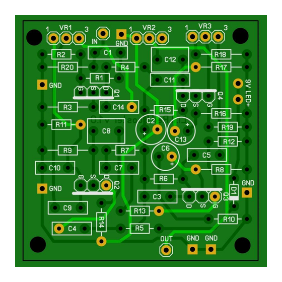
Page 5: The Finished Board
The finished board On the picture of the pot you can make out the pin sequence on the board. Blue = pin 1 White = pin 2 Yellow = pin 3... -
Page 6: Offboard Wiring
Offboard wiring Anode (long leg) Cathode (short leg) R led Sleeve Ring Ring Output Jack Input Jack Footswitch Notice that in the “off” position the effect input is connected to ground to prevent possible oscillation. The LED requires a resistor (R led in the diagram) depending on the type of LED you are using. An ultra-bright red or blue LED requires a 4k7 resistor, Green requires 680R. -
Page 7: Adding The Buffer
Adding the buffer Build the buffer as mentioned in the separate building instructions. To add it to the booster, wire it as follows: Anode (long leg) Cathode (short leg) Anode (long leg) Cathode (short leg) Sleeve Ring Ring Input Jack Output Jack Boost sw Buffer sw... -
Page 8: Troubleshooting
Troubleshooting All PCB’s have been e-tested 100% in the factory, so there should not be a connection problem on the PCB itself. The board is not working (at all), what now? Check if your 9V is plugged in correctly (and/or soldered correctly on the board). ... -
Page 9: Schematic
Schematic...
Need help?
Do you have a question about the L'ill Red Booster and is the answer not in the manual?
Questions and answers