Table of Contents
Advertisement
Quick Links
Advertisement
Table of Contents

Related Manuals for Lithium Grim Cave Vibe


Summary of Contents for Lithium Grim Cave Vibe
- Page 1 Cave Vibe Building instructions V1.0...
-
Page 2: Table Of Contents
Cave Vibe v1.0 Table of contents Components ............................3 PCB layout ............................... 4 Bill of Materials............................4 Introduction ............................. 6 Building sequence ........................... 6 Off board wiring ............................7 Testing and mods ............................ 9 Troubleshooting ............................ 10 Known problem LFO .......................... 10 Schematic .............................. -
Page 3: Components
Cave Vibe v1.0 Components Name Value Comment Name Value Comment 100n B25k Throb A100k Level 220n B100k Dual Rate 100p Ceramic B25k Intensity B10k Voice 470p Ceramic 1% metal film Electrolyte 1% metal film Electrolyte 1% metal film 100n 1% metal film... -
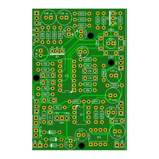
Page 4: Pcb Layout
Cave Vibe v1.0 PCB layout 50 mm x 75 mm 1.97 in x 2.95 in All trademarks held by Earthquaker Devices. Manufacturer and product names are mentioned solely for circuit identification, and where applicable their trademarks are the property of their respective owners who are in no way associated or affiliated with the author. No cooperation or... -
Page 5: Bill Of Materials
Cave Vibe v1.0 Bill of Materials Capacitors Resistors (1% metal film) Component pcs. Type Rating Component pcs. Value pcs. 100p 1 Ceramic 25V+ GL-5539 4 47k 470p 1 Ceramic 25V+ 100R 1 56k 1 MKT 25V+ 3 100k 1 SMF... -
Page 6: Introduction
Cave Vibe v1.0 Introduction The Cave Vibe is a unique vibe effect. It has been specially adapted to include an internal 18v charge- pump to provide more headroom to the effect. This charge-pump is made switchable so you can bring it back to the original if needed. This effect functions best with a 9V wallwart adapter and it is advised not to use 9V batteries. -
Page 7: Off Board Wiring
Cave Vibe v1.0 Off board wiring Wiring the pots P1,P2,P4 and P5 is very simple. The rectangle pad marks pin 1 of a potentiometer. The images below show how you can recognize which pin is which on a potentiometer. PS. You can break off the pin I marked with the yellow circle with a small pair of pliers. - Page 8 Cave Vibe v1.0 After wiring the potentiometers you will need to wire the input, output and LED : R led Sleeve Sleeve Ring NB. When switching between 9V and 18V you will need to re-adjust the intensity as the 18V setting will also make the effect LED (D4) burn more intense.
-
Page 9: Testing And Mods
Cave Vibe v1.0 Testing and mods Testing this effect is best done in a dark environment. Most importantly you should try to shield the LDR/LED’s from outside light because this will affect the working of the effect drastically. You can make a shield out of almost anything. -
Page 10: Troubleshooting
Cave Vibe v1.0 Troubleshooting All PCB’s have been 100% factory e-tested and out of every batch I receive I build an effect to double check, so there should not be a connection problem on the PCB itself. The board is not working (at all), what now? •... -
Page 11: Schematic
Cave Vibe v1.0 Schematic All trademarks held by Earthquaker Devices. Manufacturer and product names are mentioned solely for circuit identification, and where applicable their trademarks are the property of their respective owners who are in no way associated or affiliated with the author. No cooperation or...
Need help?
Do you have a question about the Cave Vibe and is the answer not in the manual?
Questions and answers