Advertisement
Advertisement
Table of Contents

Related Manuals for Lithium Grim Autowah


Summary of Contents for Lithium Grim Autowah
- Page 1 Autowah Building instructions V1.1...
- Page 2 Table of contents Components ............................3 General guideline for components......................4 General building tips ..........................4 Modifications ............................5 Offboard wiring ............................5 Troubleshooting ............................7 Schematic ..............................8 Read this entire manual thoroughly before you start to building the effect! Especially the Building and Modification part.
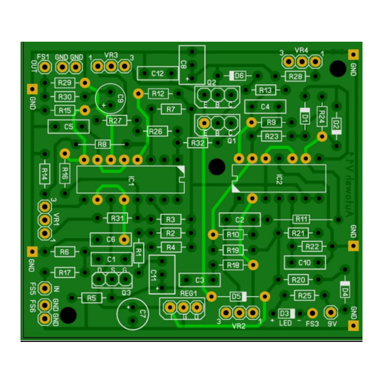
- Page 3 Components 1N4148 330R 1N4148 220n 330R 1N5817 1N4001 1N4148 100u 330R R24 10k/20k IC1 LM13700 TL074 100n REG1 LM78L05 100n 330R 330R 100k VR1 (RESONANCE) B50k (lineair) BC550C VR2 (SENSITIVITY) B100k (lineair) BC550C VR3 (BIAS) B50k (lineair) 2N5457 VR4 (DECAY) C1M (reverse log)
- Page 4 General guideline for components Capacitors: All values under 1nF should be ceramic disks. From 1nF up to 1uF should be MKT or SMF (metal film capacitors). For over 1uF use electrolyte caps 16V+ rated and watch out for polarity! C9 is also electrolyte. ...
- Page 5 Modifications You can try to replace D6 (1n4148) with a 1N34 for smoother operation. You can also experiment with other diodes. To do this you can solder 2 IC pins in the holes of D6 so you can easily mount different diodes. ...
- Page 6 Notice that in the “off” position the effect input is connected to ground to prevent possible oscillation. If you are using your own 3PDT PCB then you should not install R25 and only connect the +9V side of your 3PDT PCB to the R25 hole next to the +9V on the autowah PCB.
- Page 7 Troubleshooting All PCB’s have been e-tested 100% so there should not be a connection problem on the PCB itself. The board is not working (at all), what now? Check that you oriented the capacitors, IC’s ,transistors and diodes the right way. MKT capacitors and resistors do not need to be oriented.
- Page 8 Schematic...
Need help?
Do you have a question about the Autowah and is the answer not in the manual?
Questions and answers