Table of Contents
Advertisement
Quick Links
Advertisement
Table of Contents

Related Manuals for Lithium Grim OmniRat


Summary of Contents for Lithium Grim OmniRat
- Page 1 OmniRat Building instructions v1.0...
-
Page 2: Table Of Contents
OmniRat v1.0 Table of contents PCB layout ............................... 3 Components ............................4 Configurations ............................. 4 Build sequence ............................5 Off board wiring ............................6 Potentiometers............................ 6 Diode Switch ............................6 Modifications ............................7 OpAmp ..............................7 Drill instructions ............................8 Troubleshooting ............................ -
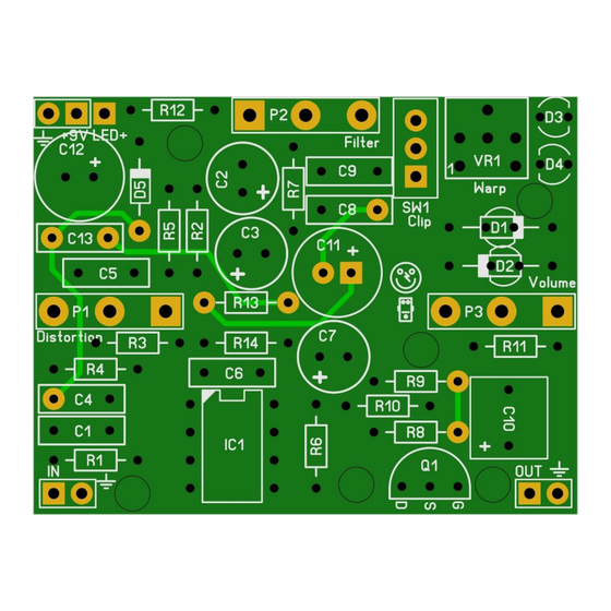
Page 3: Pcb Layout
OmniRat v1.0 PCB layout Dimensions: 49,5 mm x 38 mm 1.95 inch x 1.50 inch Manufacturers and product names are mentioned solely for circuit identification, and where applicable their trademarks are the property of their respective owners who are in no way associated or affiliated with the author. No cooperation or endorsement... -
Page 4: Components
OmniRat v1.0 Components Part Value Type Part Value Type 1% metal film Electrolytic 25V+ 560R 1% metal film Electrolytic 25V+ 1% metal film 1% metal film 100p MLCC/Silver Mica 1% metal film MLCC/Silver Mica 1% metal film Electrolytic 25V+ 1% metal film... -
Page 5: Build Sequence
OmniRat v1.0 Build sequence Before starting with this section, make sure you have read the configurations section first! Soldering this board can be very complicated for some people since the solder pads are very close together. Use a magnifying glass to make the job easier. -
Page 6: Off Board Wiring
OmniRat v1.0 Off board wiring Potentiometers In the pictures below you see the correct pin numbering of the pots (Alpha 16mm style). Solder the wires accordingly and it is always a good idea to twist the wires together to create some extra shielding against external noise. -
Page 7: Modifications
OmniRat v1.0 Rled Input Sleeve Output Ring Sleeve Rled can be somewhere between 1k5 and 10k (try 4k7). The lower the value the brighter the LED shines, but at the cost of power consumption and wear of the LED. The diagram is also based on star wiring where all ground connections go to the sleeve of the input jack. -
Page 8: Drill Instructions
OmniRat v1.0 Drill instructions Volume Distortion 17,8mm 17,8mm 17,8mm Tone/Filter Holes for the potentiometers should be 7mm. Troubleshooting All PCB’s have been 100% factory e-tested and out of every batch I receive I build an effect to double check, so there should not be a connection problem on the PCB itself. -
Page 9: Schematic
OmniRat v1.0 Schematic Manufacturers and product names are mentioned solely for circuit identification, and where applicable their trademarks are the property of their respective owners who are in no way associated or affiliated with the author. No cooperation or endorsement...
Need help?
Do you have a question about the OmniRat and is the answer not in the manual?
Questions and answers