Table of Contents
Advertisement
Quick Links
Advertisement
Table of Contents

Subscribe to Our Youtube Channel
Related Manuals for Lithium Grim Heavenly Red


Summary of Contents for Lithium Grim Heavenly Red
- Page 1 Heavenly Red Building instructions v1.0...
-
Page 2: Table Of Contents
Heavenly Red v1.0 Table of contents PCB layout ............................... 3 Components ............................4 Power section ............................5 Hardwire to 18V ..........................5 9V only ..............................5 Output buffer ............................5 Build sequence ............................5 Off board wiring ............................6 Potentiometers............................ 6 Switches ............................... -
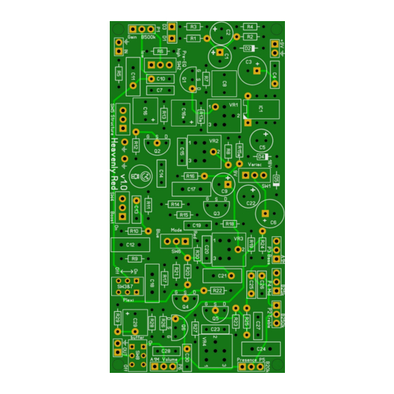
Page 3: Pcb Layout
Heavenly Red v1.0 PCB layout Dimensions: 100 mm x 49,5 mm 3.94 inch x 1.95 inch Manufacturers and product names are mentioned solely for circuit identification, and where applicable their trademarks are the property of their respective owners who are in no way associated or affiliated with the author. No cooperation or endorsement... -
Page 4: Components
Heavenly Red v1.0 Components Name Value Comment Name Value Comment Electrolytic 25V+ 390R 1% metalfilm Electrolytic 25V+ 1% metalfilm 100u Electrolytic 25V+ 390R 1% metalfilm 100n SMF/MKT/Wima 1% metalfilm Electrolytic 25V+ 1% metalfilm 100u Electrolytic 25V+ 1% metalfilm SMF/MKT/Wima 820R... -
Page 5: Power Section
Heavenly Red v1.0 Power section IC1 can be either a LT1054 or a (cheaper) ICL7660S. I do not advise the use of a battery in this build as the charge pumps will do strange things when the battery is depleted. This is why it is also left out in the off board wiring section. -
Page 6: Off Board Wiring
Heavenly Red v1.0 Now continue by soldering the MLCC, small SMF/MKT/Wima capacitors then solder the internal trim pots (VR1-VR4). Now finish by soldering the transistors (if not socketed), the bigger MKT/WIMA and the electrolytic capacitors. I suggest you now drill the holes in your enclosure so you can use it during the off board wiring. This PCB is very sensitive to noise! Keep the wires as short as possible and/or use shielding on the input and output. -
Page 7: Plexi Switch Function
Heavenly Red v1.0 Sleeve Output On/Bypass Boost Ring Sleeve Input The LED switching is made as described by AMZ’s anti Led pop setup. No need for an external LED current limiting resistor. Keep cables as short as possible to prevent interference! Plexi switch function When engaging the Plexi switch (SW3&7) the Mode switch (SW6), Boost switch (SW4) and Structure... -
Page 8: Biasing
Heavenly Red v1.0 Biasing Biasing this effect is very difficult. Start by setting the following switches: • Variac +9V • Boost Off • Red Channel • Plexi Off • Structure Off • Buffer Off • Pre-EQ to taste Set the pots as follows: •... -
Page 9: Modifications
Heavenly Red v1.0 Modifications Structure The original only has a structure on-off. In this version I added an extra option for a second structure option formed by C16a and R13a. After some experimenting I found the 1uF/15k combination to have some added value, but feel free to experiment and let me know if you found a good combination. -
Page 10: Schematic
Heavenly Red v1.0 Schematic Manufacturers and product names are mentioned solely for circuit identification, and where applicable their trademarks are the property of their respective owners who are in no way associated or affiliated with the author. No cooperation or endorsement...
Need help?
Do you have a question about the Heavenly Red and is the answer not in the manual?
Questions and answers