Table of Contents
Advertisement
Quick Links
Advertisement
Table of Contents

Related Manuals for Lithium Grim SnoWahFlake


Summary of Contents for Lithium Grim SnoWahFlake
- Page 1 SnoWahFlake Building instructions V2.0...
-
Page 2: Table Of Contents
SnoWahFlake v2.0 Table of contents PCB layout ............................... 3 Components ............................4 Modifications ............................5 Build sequence ............................6 Off board wiring ............................7 Potentiometers............................ 7 Side Chaining ............................7 Footswitches and stargrounding ......................8 Troubleshooting ............................9 Schematic .............................. 10... -
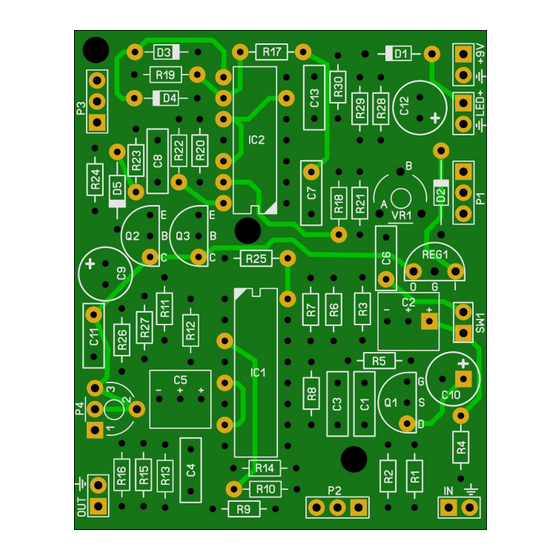
Page 3: Pcb Layout
SnoWahFlake v2.0 PCB layout Dimensions: 50 mm x 60,5 mm 1.97 inch x 2.38 inch Manufacturers and product names are mentioned solely for circuit identification, and where applicable their trademarks are the property of their respective owners who are in no way associated or affiliated with the author. No cooperation or endorsement... -
Page 4: Components
SnoWahFlake v2.0 Components Name Value Comment Name Value Comment 1% metalfilm 1% metalfilm 1% metalfilm 1% metalfilm 1% metalfilm 220n 330R 1% metalfilm 330R 1% metalfilm 1% metalfilm Electrolyte 1% metalfilm 100u Electrolyte 1% metalfilm 100n 330R 1% metalfilm Electrolyte... -
Page 5: Modifications
SnoWahFlake v2.0 Modifications There are different ways to build this effect. The components list above is based on the modded version of the original. Original Optimized Modded VR1* 20k 50k* 1N4148 1N34A 1N34A jumper jumper Switching jack LM324 TL074 TL074... -
Page 6: Build Sequence
SnoWahFlake v2.0 Build sequence Soldering this board can be very complicated for some people since the solder pads are very close together. Use a magnifying glass to make the job easier. The trick to soldering a PCB is to work from small to big components. -
Page 7: Off Board Wiring
SnoWahFlake v2.0 Off board wiring Potentiometers In the pictures below you see the correct pin numbering of the pots (Alpha 16mm style). Solder the wires accordingly and it is always a good idea to twist the wires together to create extra shielding against external noise. -
Page 8: Footswitches And Stargrounding
SnoWahFlake v2.0 Footswitches and stargrounding Anode (long leg) Cathode (short leg) R led Ring Ring Sleeve Input Jack Output Jack Footswitch Note that R led is a 4k7 resistors. You can change this value depending on the type of LED you use but 4k7 is safe enough for almost all LEDs @ 9V. -
Page 9: Troubleshooting
SnoWahFlake v2.0 Troubleshooting All PCB’s have been 100% factory e-tested and out of every batch I receive I build an effect to double check, so there should not be a connection problem on the PCB itself. The board is not working (at all), what now? •... -
Page 10: Schematic
SnoWahFlake v2.0 Schematic Manufacturers and product names are mentioned solely for circuit identification, and where applicable their trademarks are the property of their respective owners who are in no way associated or affiliated with the author. No cooperation or endorsement...
Need help?
Do you have a question about the SnoWahFlake and is the answer not in the manual?
Questions and answers