Table of Contents
Advertisement
Quick Links
Advertisement
Table of Contents

Subscribe to Our Youtube Channel
Related Manuals for Lithium Grim Klonulator


Summary of Contents for Lithium Grim Klonulator
- Page 1 Klonulator Building instructions v1.0 Last update: 22-10-2019...
-
Page 2: Table Of Contents
Klonulator v1.0 Table of contents PCB layout ............................... 4 Components ............................5 Bill of Materials............................6 Introduction ............................. 7 Build sequence ............................7 Enclosure (drilling) ..........................7 Populating the PCB ..........................8 Off board wiring ............................9 Potentiometers non PCB mounted ..................... 9 Potentiometers PCB mounted ...................... - Page 3 Klonulator v1.0 Silver Pony ............................16 1994 specs ............................16 Troubleshooting ............................ 16 Drill Templates ............................17 Topside Hammond 1590BB ....................... 17 Back side Jacks Hammond 1590BB ....................17 Schematic .............................. 18 Manufacturers and product names are mentioned solely for circuit identification, and where applicable their trademarks are the property of their respective owners who are in no way associated or affiliated with the author.
-
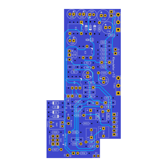
Page 4: Pcb Layout
Klonulator v1.0 PCB layout Dimensions: 100 mm x 49,6 mm 3.94 inch x 1.95 inch Manufacturers and product names are mentioned solely for circuit identification, and where applicable their trademarks are the property of their respective owners who are in no way associated or affiliated with the author. No cooperation or endorsement... -
Page 5: Components
Klonulator v1.0 Components Name Value Comment Name Value Comment 100n SMF/MKT/Wima P1A* B100k Gain Dry Electrolytic 25V+ P1B* B100k Gain Wet 100n SMF/MKT/Wima B10k Tone SMF/MKT/Wima B10k Output SMF/MKT/Wima R1 ** 1% metalfilm 390n SMF/MKT/Wima 1% metalfilm SMF/MKT/Wima 100k 1% metalfilm... -
Page 6: Bill Of Materials
Klonulator v1.0 Bill of Materials Name Value Type Amount Name Value Type Amount 390p SMF/MKT/Wima 560R 1% metalfilm 820p SMF/MKT/Wima 1% metalfilm SMF/MKT/Wima 1% metalfilm SMF/MKT/Wima 1% metalfilm SMF/MKT/Wima 1% metalfilm SMF/MKT/Wima 1% metalfilm SMF/MKT/Wima 1% metalfilm 100n SMF/MKT/Wima 1% metalfilm... -
Page 7: Introduction
Klonulator v1.0 Introduction The Klonulator is based on Bill Finnegans famous Klon Centaur™. While sticking close to the original, I added a few optional onboard modifications and dedicated an entire modifications section in this manual so you can add your own flavor to the effect (only if you want to of course). Read the entire manual before you start building. -
Page 8: Populating The Pcb
Klonulator v1.0 Pots need a 7 mm hole, footswitches 13 mm, other switches (Gain boost and/or Diodes) need 6 mm holes and the LED is either 5 mm or 3 mm depending on your choice of LED. Diameters might differ with different brands of switches, so before drilling the holes, measure if it fits!!!!! The 36,5 mm for the gain boost hole is just a suggestion based on the switch I used. -
Page 9: Off Board Wiring
Klonulator v1.0 Off board wiring You can either mount the potentiometers directly to the PCB with special potentiometers or use the more traditional solder lug potentiometers. Potentiometers non PCB mounted In the pictures below you see the correct pin numbering of the pots (Alpha 16mm style). -
Page 10: Switches
Klonulator v1.0 Switches Gain boost Clipping diodes If you want to be able to switch the diodes externally and not via the internal DIP switch, then leave out the DIP and wire it like this using a SP3T (ON/OFF/ON) switch: Or as a DP3T On/Z/On switch so you can also switch all diodes on (but not off!) Test the pole that are active in the middle position before you solder it. -
Page 11: Original Wiring (Buffered Bypass)
Klonulator v1.0 Original wiring (Buffered bypass) Status Sleeve Ring Sleeve Input Output There is no wire from the output sleeve to ground so make sure there is good electrical contact between the jack and the enclosure, else you will need to solder a wire from the output sleeve to the input sleeve. -
Page 12: True Bypass Wiring
Klonulator v1.0 True bypass wiring There are several ways to fit true bypass to this PCB. First off I suggest you leave out the output mixer resistors (both 68k). If you really want to, you can keep the 100k between the output jack and ground although not really necessary. -
Page 13: Klon Bypass Pcb
Klonulator v1.0 Klon Bypass PCB When you bought a klon bypass PCB, you can solder and wire it up as follows. RA and RB are 68k. RC is 100k. Some clones do not use RA. The miniature DPDT switch lets you switch between regular buffered bypass and true bypass. -
Page 14: Modifications
Klonulator v1.0 Modifications Bare bones power section Some do not see the added value of the charge pump as it is only there to keep IC2 from clipping. There are however clipping diodes before IC2 is reached so that way you can doubt the use of the charge pump. -
Page 15: Clipping Diode Section
Klonulator v1.0 Clipping diode section The Diode section has a lot of options. Let’s walk through the standard layout. There have been many discussions on which diodes were used and finally the D9E and/or 1N34A were designated as “originals”. This version of the PCB offers you the change to experiment. I suggest you put the originals in D2 and D3, and your choice of diodes in D4 and D5. -
Page 16: Silver Pony
Klonulator v1.0 Silver Pony Also a well-known mod based on the reverse-engineered silver Centaur, serial S2207 (by Build Your Own Clone). The brought up some different valued components. Changing R10 to 47R will give you some more gain. Changing R17 to 10k and R18 to 4k7 will give more volume and treble for the dry signal. -
Page 17: Drill Templates
Klonulator v1.0 Drill Templates Topside Hammond 1590BB Back side Jacks Hammond 1590BB Manufacturers and product names are mentioned solely for circuit identification, and where applicable their trademarks are the property of their respective owners who are in no way associated or affiliated with the author. No cooperation or endorsement... -
Page 18: Schematic
Klonulator v1.0 Schematic Manufacturers and product names are mentioned solely for circuit identification, and where applicable their trademarks are the property of their respective owners who are in no way associated or affiliated with the author. No cooperation or endorsement...
Need help?
Do you have a question about the Klonulator and is the answer not in the manual?
Questions and answers