Table of Contents
Advertisement
Quick Links
Advertisement
Table of Contents

Subscribe to Our Youtube Channel
Related Manuals for Lithium Grim Cabulator


Summary of Contents for Lithium Grim Cabulator
- Page 1 Cabulator Building instructions v1.0...
-
Page 2: Table Of Contents
Cabulator v1.0 Table of contents PCB layout ............................... 3 Components ............................4 Build sequence ............................5 Drill template ............................6 Off board wiring ............................7 Switches ..............................8 SW1 ..............................8 Hardwired ............................8 DP3T switch ............................. 8 XLR Out and SW2 ..........................9 Modifications ............................ -
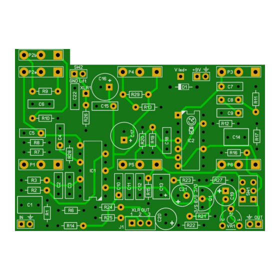
Page 3: Pcb Layout
Cabulator v1.0 PCB layout Dimensions: 75 mm x 54,6 mm 2.95 inch x 2.15 inch Manufacturers and product names are mentioned solely for circuit identification, and where applicable their trademarks are the property of their respective owners who are in no way associated or affiliated with the author. No cooperation or endorsement... -
Page 4: Components
Cabulator v1.0 Components Name Value Comment Name Value Comment 470n SMF/MKT/Wima Q1 2N2222A 100n SMF/MKT/Wima R1 1% metalfilm 100n SMF/MKT/Wima R2 1% metalfilm 470p MLCC 1% metalfilm SMF/MKT/Wima R6 1% metalfilm SMF/MKT/Wima R7 1% metalfilm SMF/MKT/Wima R8 1% metalfilm SMF/MKT/Wima R9... -
Page 5: Build Sequence
Cabulator v1.0 Build sequence Soldering this board can be very complicated for some people since the solder pads are very close together. Use a magnifying glass to make the job easier. The trick to soldering a PCB is to work from small to big components. My building sequence suggestions in this section are based on the parts I used myself. -
Page 6: Drill Template
Cabulator v1.0 Besides the components mentioned in the components table, you will need: • 1 mono input jack, 1 stereo output jack. • 3PDT footswitch (9 pins) • 2,1mm DC jack (isolated). • 22 gage stranded hook-up wire. • LED holder. This enables you to mount the LEDs in the enclosure. -
Page 7: Off Board Wiring
Cabulator v1.0 Off board wiring Sleeve Sleeve Ring Output Input R led is a 3k3/4k7 resistors. You can change the value depending on the type of LED you use but 4k7 is safe enough for almost all LEDs @9V. Note that the diagram is using star wiring for the ground connection. This requires that the output jack makes very good contact to the enclosure! If this is not possible, you can connect a wire to the sleeve of the output jack and the sleeve of the input jack. -
Page 8: Switches
Cabulator v1.0 Switches SW1 determines the output of the PCB. You can choose to attach a switch or to hardwire it. If you attach a DP3T on-Z-on switch, you can choose between normal out via the output jack, output via both XLR and normal out and XLR out only. -
Page 9: Xlr Out And Sw2
Cabulator v1.0 XLR Out and SW2 You can use the XLR out with or without a ground lift switch (SW2). If you do not want to use the ground lift then you can leave out C22 and R26. Turning VR1 will pad the output of the XLR if it is too loud. -
Page 10: Modifications
Cabulator v1.0 Modifications The PCB was designed to enable you to make several different mods. There were a lot of experiments with making the effect sound even better, mainly by Bajaman. All these versions have their good sides so you can build any of them by using only this single board. The only thing you will have to do is choose. -
Page 11: Optimized Version
Cabulator v1.0 Optimized version Name Value Comment Name Value Comment 470n SMF/MKT/Wima Q1 2N2222A 120n SMF/MKT/Wima R1 1% metalfilm 120n SMF/MKT/Wima R2 1% metalfilm SMF/MKT/Wima R3 1% metalfilm SMF/MKT/Wima R6 1% metalfilm SMF/MKT/Wima R7 1% metalfilm SMF/MKT/Wima R8 1% metalfilm... -
Page 12: Troubleshooting
Cabulator v1.0 Troubleshooting All PCB’s have been 100% factory e-tested and out of every batch I receive I build an effect to double check, so there should not be a connection problem on the PCB itself. The board is not working (at all), what now? •... -
Page 13: Schematics
Cabulator v1.0 Schematics Manufacturers and product names are mentioned solely for circuit identification, and where applicable their trademarks are the property of their respective owners who are in no way associated or affiliated with the author. No cooperation or endorsement... - Page 14 Cabulator v1.0 Manufacturers and product names are mentioned solely for circuit identification, and where applicable their trademarks are the property of their respective owners who are in no way associated or affiliated with the author. No cooperation or endorsement is implied.
- Page 15 Cabulator v1.0 Manufacturers and product names are mentioned solely for circuit identification, and where applicable their trademarks are the property of their respective owners who are in no way associated or affiliated with the author. No cooperation or endorsement is implied.
Need help?
Do you have a question about the Cabulator and is the answer not in the manual?
Questions and answers